
The voltmeter and ammeter circuits are practically no different from those recommended by the manufacturers of this microcircuit. A feature is compact performance.
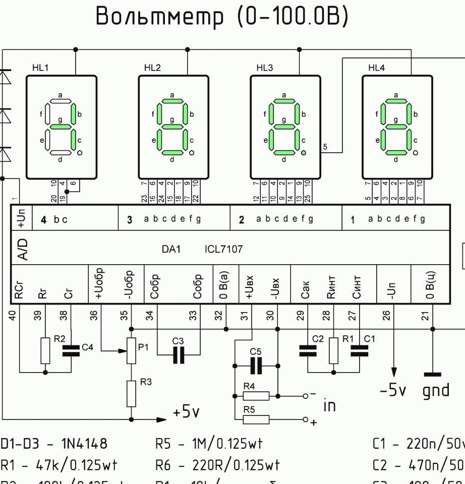
Voltmeter.
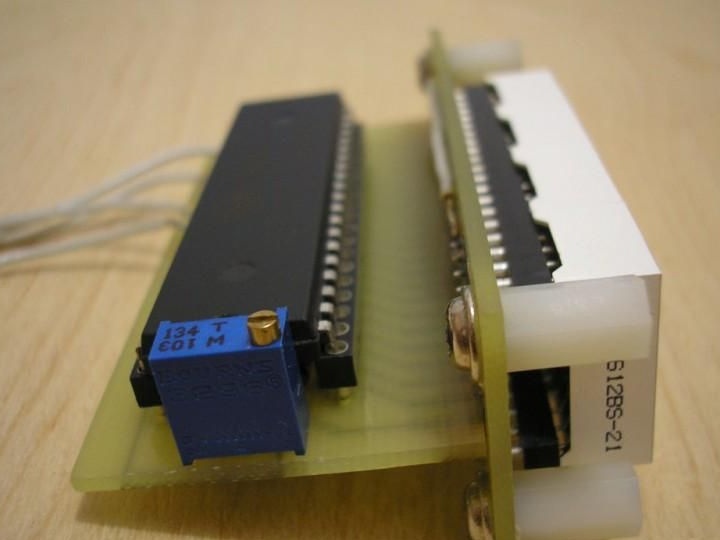
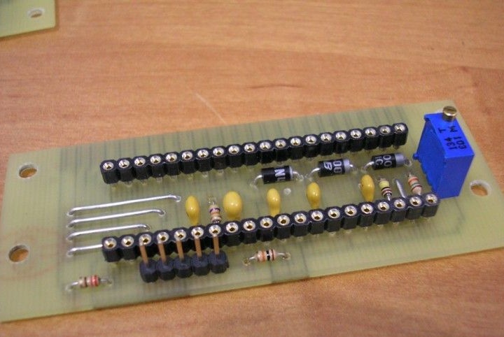
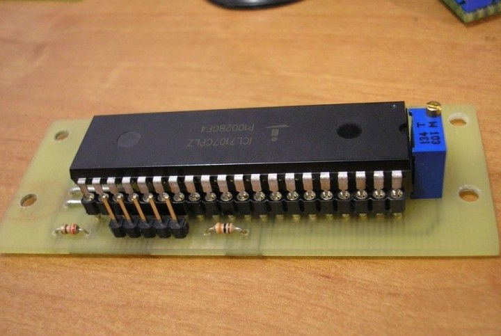
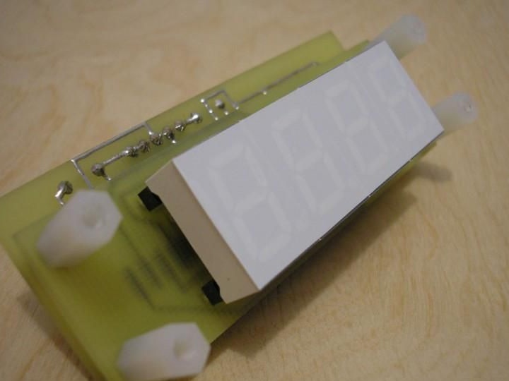
The first version of the device is assembled on two boards interconnected by the letter T. On the first board there are seven-segment indicators, on the second - a microcircuit and strapping details. For greater compactness, parts are placed under the chip.

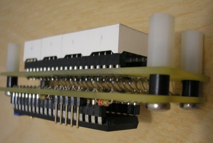
But even such a design has a sufficient volume, and it was decided to assemble the second design by installing boards in parallel. In the photographs, you can track the order of assembly. By the number of diodes D1-D3 connected in series, you can adjust the brightness of the indicators (using only two diodes, the brightness will be higher).
Assembly.
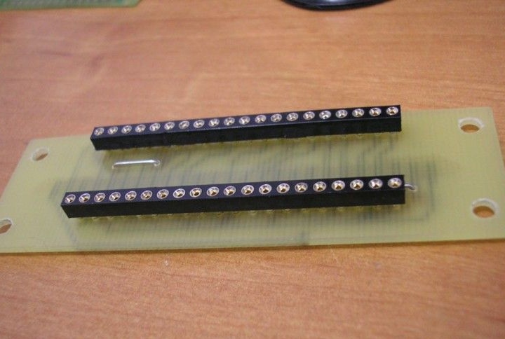
Board with and without microcircuit.
Display board
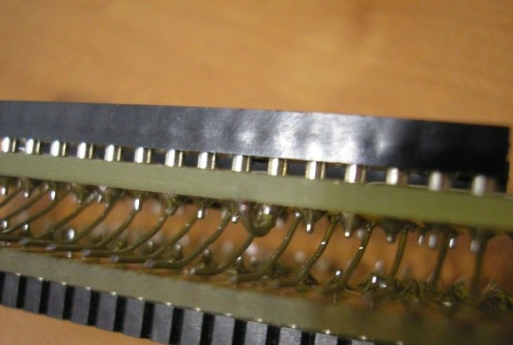
Then jumpers are soldered to the display board at an angle of 30 degrees
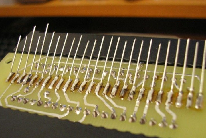
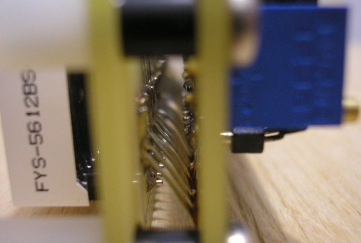
After this, the boards are folded by soldering to each other. Long jumpers are neatly cut off and soldered to an adjacent board. As a result, we get a finished, compact design.
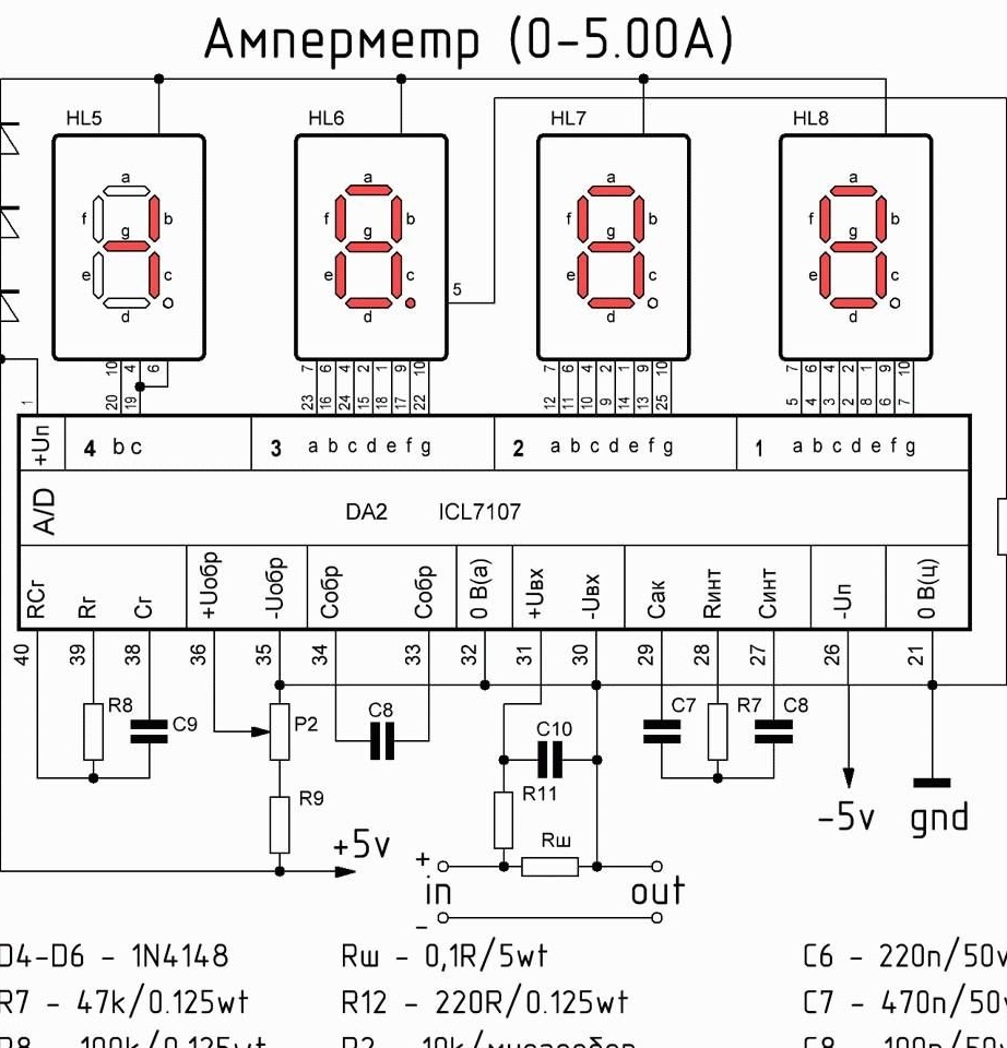
Ammeter.
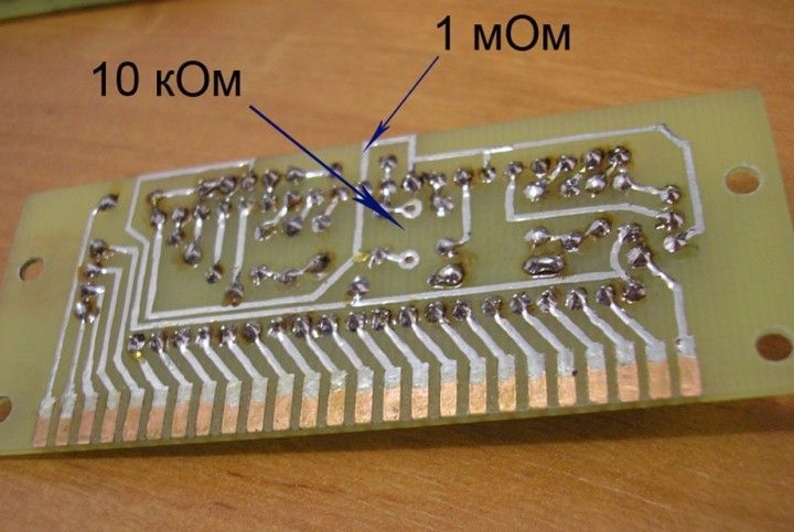
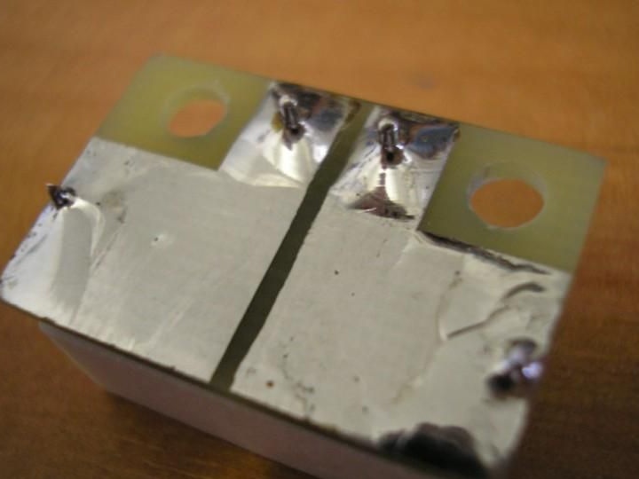
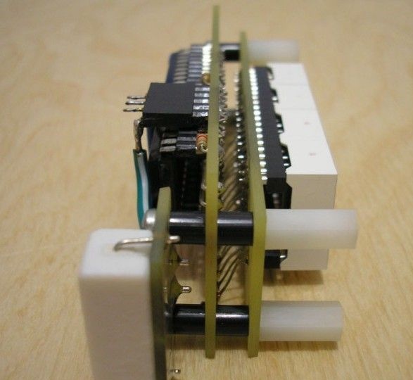
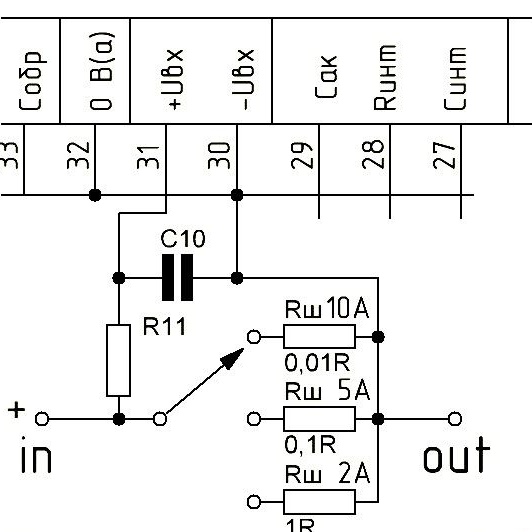
The design is the same as that of a voltmeter, two parallel boards, paths to each other, connected by jumpers. The circuit of the ammeter differs only in the input part: instead of the 1Mohm resistor, a 10kΩ resistor is soldered, a jumper igniting a comma on the indicator is transferred, and a board with a 5 ampere shunt (resistor 0.1 Ohm, 5W) is added. All three boards are attached to each other using plastic bushings with threaded M3 threads and long screws.
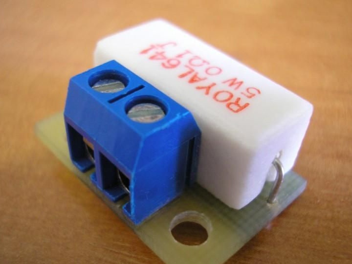
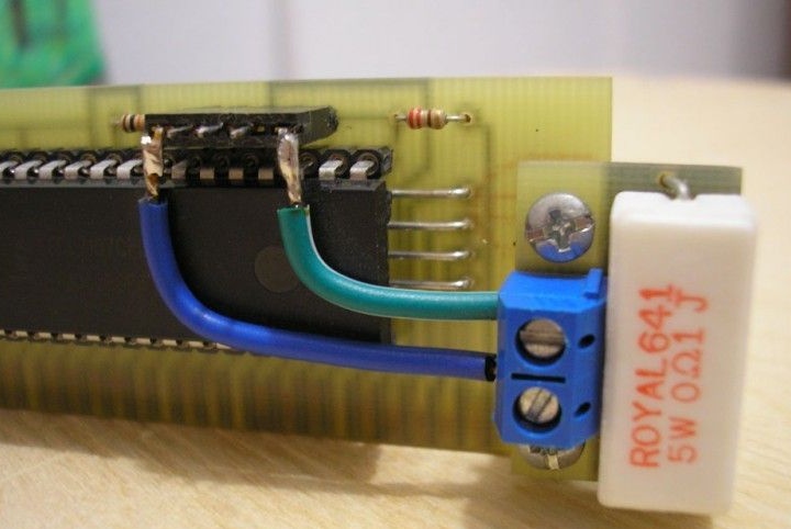
Naturally, it is possible to change the limits of current measurement by selecting the resistance of the shunt.
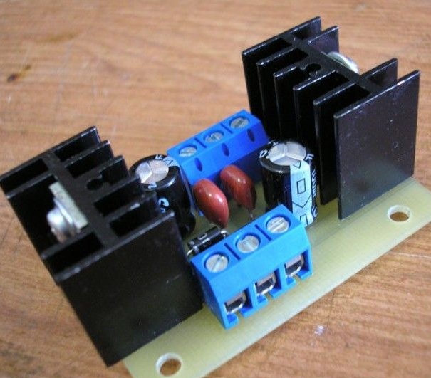
The devices must be powered from a stabilized bipolar power supply, with output voltages of +5 and -5 volts. For this, integral stabilizers 7805 and 7905 and a minimum strapping were used. All this is assembled on a separate board.
Before use, it is necessary to adjust the accuracy of the readings with tuning resistance, while measuring reference values.