Winter came, and I drove my iron horse on a well-deserved rest in garage. At this time of the year you don’t really go for a drive (except for a kiosk for a beer), but you need to do something, I decided to carry out some minor improvements, including the electrical part. Since I collected the wiring and almost everything connected with it from scratch last year, in principle, everything suited me, except for the turn relay. The relay itself on the motorcycle has already been changed to automotive, with BMW, it seems, as a company, but there was one thing: the flicker frequency. The operating voltage in the network of my Dnieper fluctuated somewhere between 11.5 - 14 volts, due to which the bulbs did not blink at a constant speed, and with an increase in the generator speed, the blink frequency increased, but decreased with a decrease. It seems to be a trifle, but still it was a little annoying. I tried to get out of the situation and set the stock relay, the result is the same. I tried to install a mechanical one from Java, so I didn’t want to work with a load of less than 20 watts, in general, I was tired of it, and I decided to assemble the relay myself.
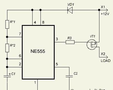
After searching the internet, I found a suitable scheme for me:

For assembly, you need such a minimum of tools and parts:
- Soldering iron, tin, acid
- Resistors on R1-22K, R2-180K and R3-2k2
- Capacitors C1-4µ7, C2-100n
- Diode VD1-1N4007
- Transistor VT1-IRF9540N
- Chip NE555
- Case for the device (any suitable in size)
A generator based on a 555 timer, flicker frequency can be adjusted with resistors R1, R2. (I got about 48 per minute), the load goes through the IRF9540N transistor.
It approached me in all respects, such as the cheapness of the assembly, the flicker frequency is stable, regardless of voltage and load, the absence of mechanical elements and it works at a current of up to 23 Amps. With these characteristics, you can install it anywhere, from a moped to a truck.
Having obtained the necessary details on the radio market (it cost me about UAH 15), I proceeded to soldering.
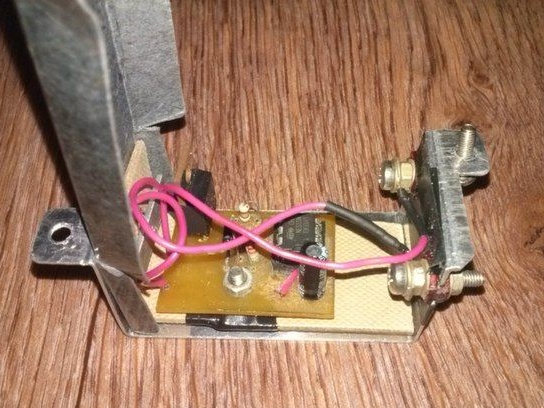
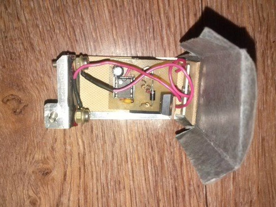
I soldered several assembly options, the most successful one turned out without a board, soldering the parts between each other and the gulf with epoxy resin, such an assembly is as tiny as possible. The device turned out to be very compact, fits into the case of a standard relay without any problems.
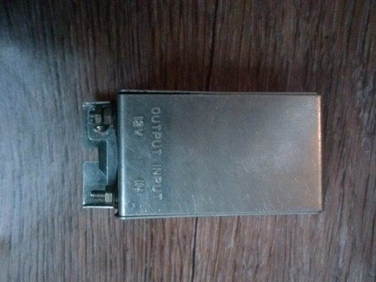
Here are photos of one of the assemblies, I etched the board myself, the case used fluorescent lamps from the throttle. It turned out not bad, but a little overall.


During testing, it gave a load of 0.06 to 100 W, while the flicker frequency remained stable. As for the radiator. With a normal load of two lamps of 5 W each, the transistor practically does not heat up, it is not necessary to install it, although of course at your discretion. In general, I got my way, the relay was installed, and in practice proved to be excellent!
