» Electronics » LEDs »Voltage indicator on three LEDs

Voltage indicator on three LEDs


In this article, the author proposes to consider the design of a voltage indicator on three LEDs.

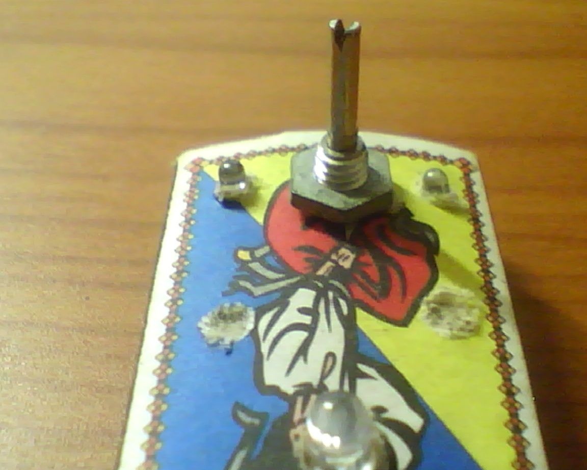
The operation of the finished device looks like this: When the nominal voltage arrives, the central (green) LED lights up, when the voltage drops, the left (red) LED lights up, when the voltage rises, the right (red) LED lights up.
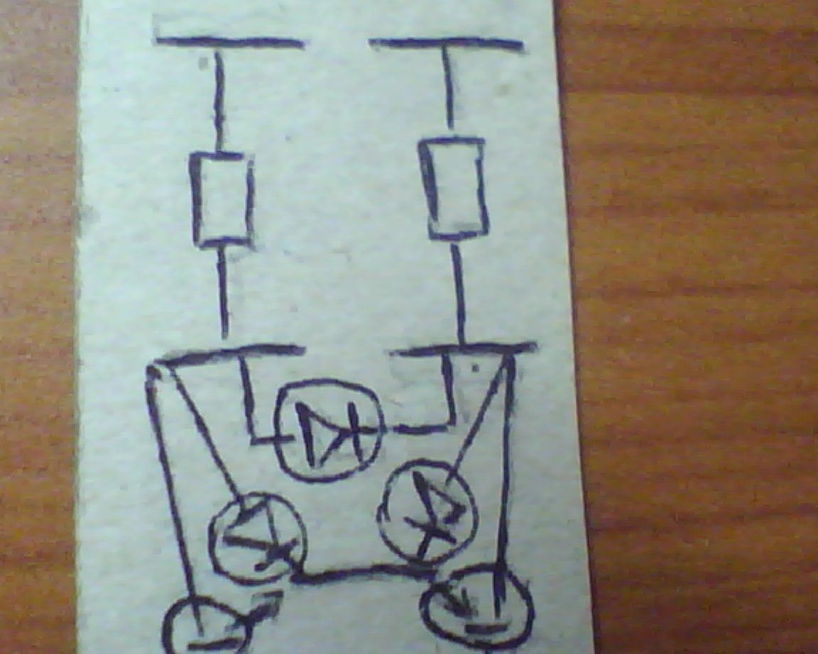
When setting the variable resistor in the "middle" position, all transistors will be closed, and the voltage will only be supplied to the green LED.

Voltage indicator on three LEDs

Moving the variable resistor slider up (raising the voltage) opens the transistor VT1, while the voltage supply to the LED HL3 stops and the voltage is supplied to the LED HL1. If the resistor slider is moved down (thereby lowering the voltage), this will close the transistor VT1 and open the transistor VT2, which will apply voltage to the LED HL2. This will cause a slight delay, the LED HL1 will stop glowing, the LED HL3 will flash once and finally HL2 will light up.


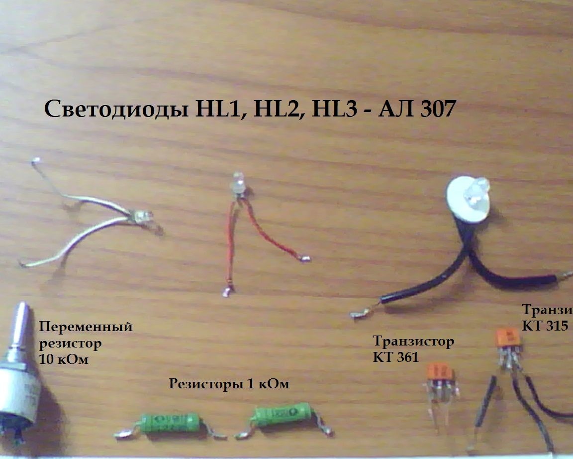
Necessary parts and tools:
- Soldering iron (tin and acid to it)
- R1 variable resistance 10 kOhm
- R2, R3 resistance 1 kOhm
- VT1 CT 315 B
- VT2 CT 361 B
- HL1 red LED
- HL2 red LED
- HL3– green LED
- X1 and X2 power supply in the form of 6V
(select LEDs with a supply voltage of 1.5 volts)
- Suitable housing for the device (the author used a matchbox)

All of these items may be present in old Soviet technology - televisions, tape recorders, radios.

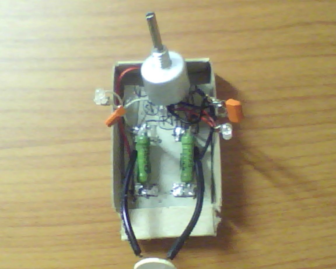
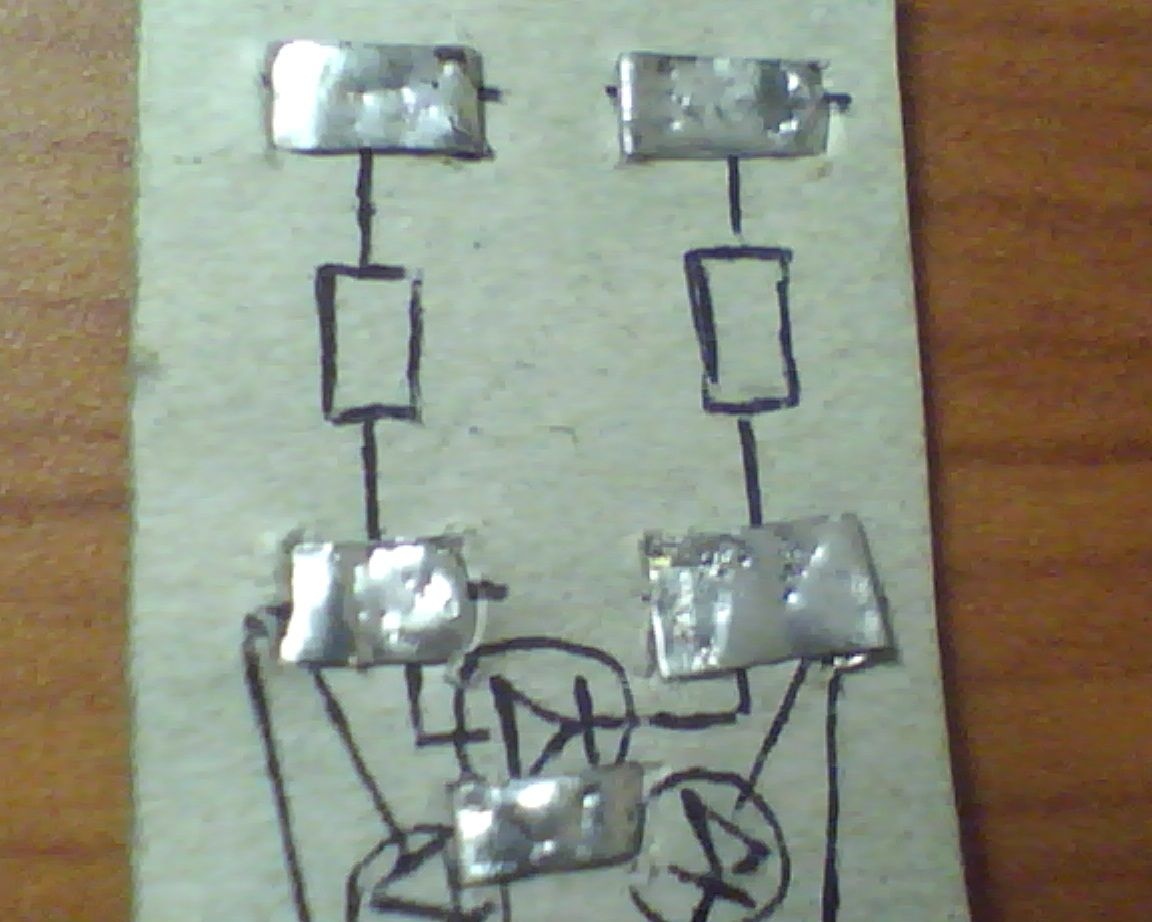
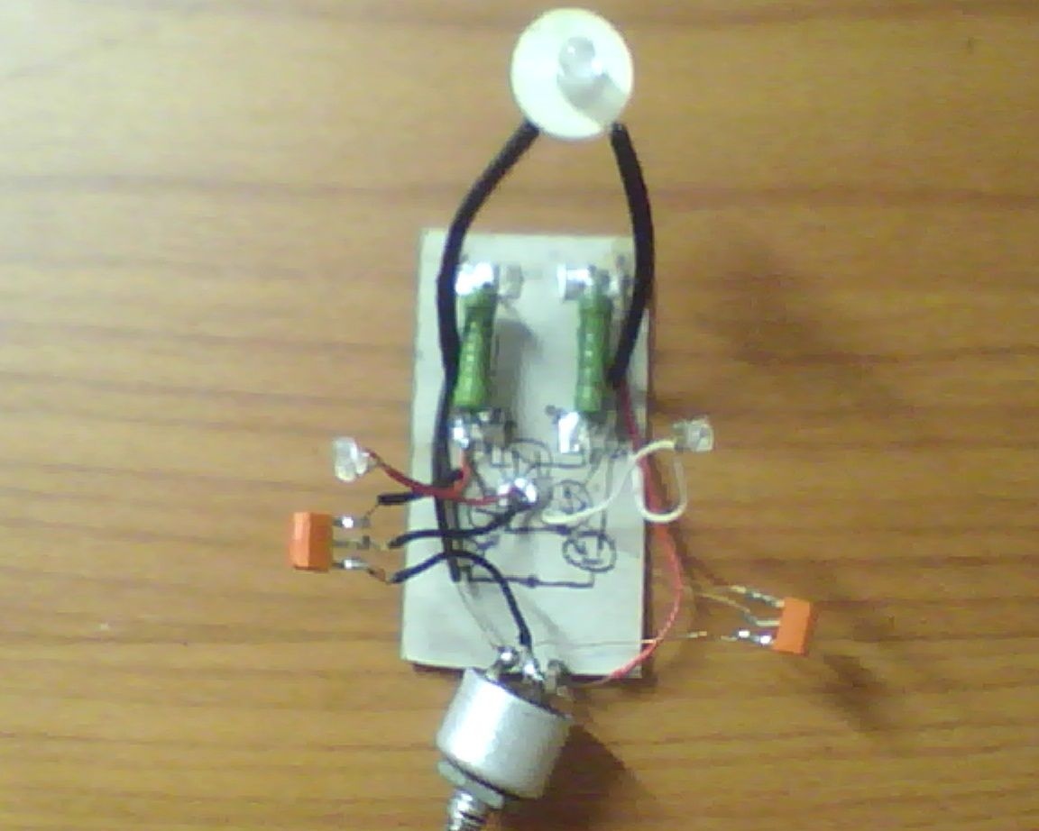
To assemble the circuit, the author used a printed circuit board from cardboard, but the circuit can be assembled both on weight and you can use a PCB for it.
A scheme of the convenient arrangement of parts and their type is applied to the cardboard board. The size is respected 1: 1 with the original part, so that later everything fits.

For platforms, the author used such proluzhonny braces cut from a can of coffee (any suitable materials can be used).

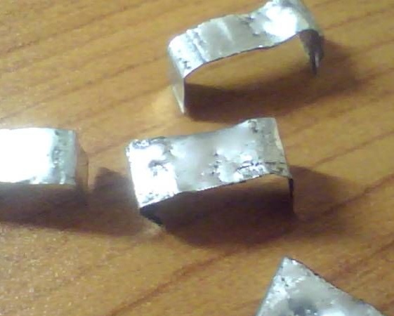
We attach brackets to the “board”.

Solder resistors and LEDs.

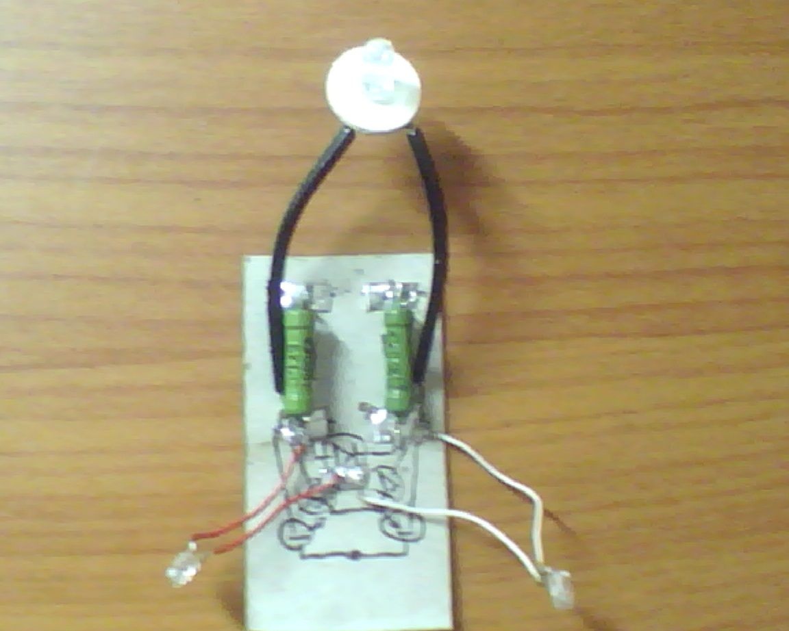
After we solder transistors and a variable resistor to control the system.

The diagram shows where the transistors output base, collector, emitter.

Next, it remains for us to place the finished board on any suitable case and the device will be completely ready for use.

7
8
7

Add a comment

    • smilesmilesxaxaokdontknowyahoonea
      bossscratchfoolyesyes-yesaggressivesecret
      sorrydancedance2dance3pardonhelpdrinks
      stopfriendsgoodgoodgoodwhistleswoontongue
      smokeclappingcraydeclarederisivedon-t_mentiondownload
      heatirefullaugh1mdameetingmoskingnegative
      not_ipopcornpunishreadscarescaressearch
      tauntthank_youthisto_clueumnikacuteagree
      badbeeeblack_eyeblum3blushboastboredom
      censoredpleasantrysecret2threatenvictoryyusun_bespectacled
      shokrespektlolprevedwelcomekrutoyya_za
      ya_dobryihelperne_huliganne_othodifludbanclose
7 comments
Quote: Apasov
Hello. How to make this, only 12 volts?

According to Google, such an indicator was sold for cars (I had one). It was inserted into the cigarette lighter, green - normal, red left - discharge, red right - recharge. But then it was no longer necessary.
It will be necessary to increase the resistance of resistors R2 and R3. I believe that twice. But I would solder something like this
Hello. How to make this, only 12 volts?
It seems to me alone that this is NOT a voltage indicator? After all, if you put the engine of the variable resistor R1 strictly in the center, then when the supply voltage changes, will the transistors remain closed? The voltage indicator will be the circuit if you put a zener diode with a nominal value slightly less than half of the monitored voltage in the gap of one of the terminal pins R1, and then adjust the indicator voltage with R1.
Ilya
Cool homemade !!! In the evening I’ll do it, there will be one LED (I will take three color)
I don’t understand why a variable resistor is needed
I've never seen LEDs on a matchbox! But the idea is, in spite of the seemingly frivolous toy, it has invaluable practical value. And the device is thought out perfectly with all the genius of its simplicity. But why not be a three-color indicator?
When using a “human” printed circuit board, a homemade product would look much neater. In the extreme case (if you do not want to mess with chemistry), you can not etch the board, but "scratch it".
p.s. The power of the resistors (and, accordingly, the dimensions) is clearly excessive ...

We advise you to read:

Hand it for the smartphone ...