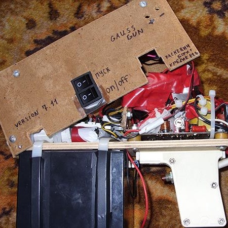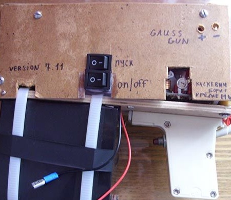
There are many homemade gauss gun projects on the Internet. The author of this article offers one of the options for its design.
The principle of operation of the device is to disperse a metal projectile with a magnetic field, based on the "Gaussian effect", named after the scientist Carl Gauss who discovered it.
This prototype is relatively safe due to the low flight speed of the projectile (according to the author, 9 meters per second) and can serve as a child’s toy for beginner electronic engineers to contemplate the “Gaussian effect” in practice.
Description of the finished device:
Weight: 2.5 kilograms
Projectile flight speed: 9 meters per second
Projectile weight: 30 grams
Recharge time (charging capacitor):
- from the battery: 2 seconds;
- from the network: 30 seconds;
Dimensions:
- length 200mm;
- width 70mm;
- height 170mm.
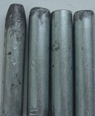
As shells, you can use any suitable metal shells in size. The main elements in the gun are coil and capacitors.
The structure of the gauss gun looks like this:
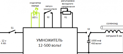
Clarification: There is a small error in the circuit, the capacitor must be used for at least 500 volts.
Multiplier Scheme:
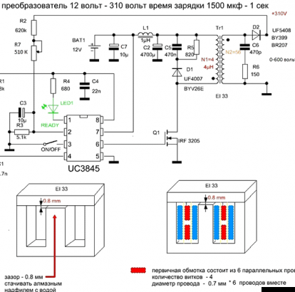
The IRF 3205 transistor used in the multiplier charges a capacitor with a capacity of 1000 microfarads to 500 volts in 2 seconds (if you use a 4 ampere battery). You can also use the IRL 3705 transistor, but with it the charging speed will drop and will be 10 seconds.
Resistor R7 is used to adjust the output voltage in the range of 50-900 volts. LED 1 indicates that the capacitors are fully charged.
If noise is heard in the transformer, it can be eliminated by selecting capacitor C1 with a lower capacity. Capacitance C2 can also be reduced to 1000 microfarads.
DO NOT apply voltage to the inputs when switch S1 is in the closed position, as this may result in transistor failure due to a power surge.
Step 1. Transformer.
We need a transformer from an unnecessary PC power supply. Boil it in boiling water for about 10 minutes and disassemble the core. It is also necessary to unwind the windings themselves.
We need a wire with a diameter of 0.5 -0.7 mm. We wind them a secondary winding, but not all but only half.The diagram indicates its beginning:
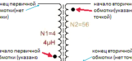
After kA wound 27 turns, you need to output the wire, but without cutting it. It is also important to remember the direction of winding the wire. After this is done, isolate these turns with paper.
The next step will be winding the turns of the primary winding. The starting point of its winding is also indicated on the diagram. The direction of winding the turns is the same as that of the secondary winding. This winding has only 4 turns. To wind the coils, we need to fasten together six wires in parallel and carefully lay them. The ends of the wires are soldered.
Just roll the secondary winding. The number of turns and the direction is the same as in the first part.
Step 2. Scheme.
If the circuit is assembled correctly, then no additional settings are required.
Photo details:
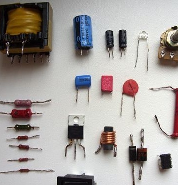
A battery will also be needed, the better it is, the capacitors will be charged faster. The project uses a 4 amp hour battery.
Photo of the assembled converter:
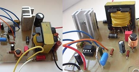
Bottom view:
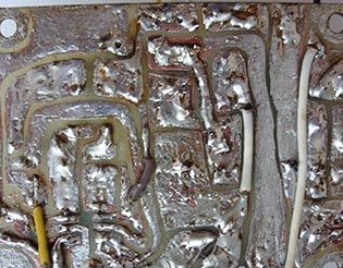
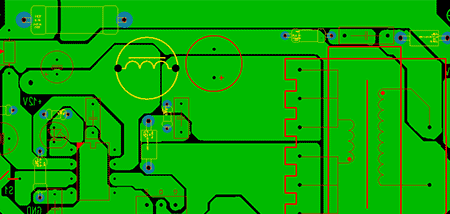
A more compact version of the board, drawn by the author in Sprint-layout.
There is also a network-based multiplier circuit:
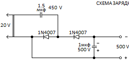
You can use any diodes that can operate with voltages above 66 volts.
The capacitor is installed with a capacitance somewhere between 0.5 - 3.3 microfarads.
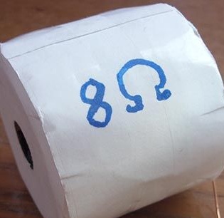
Coil resistance 8 ohms. Inside the copper wire coated with varnish, has a diameter of 0.7 mm. The length of the entire wire is about 90 meters.
Step 3. The gun.
For her, you need a sheet of plywood 200x70mm in size.

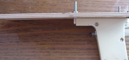
We attach a handle to it. It can be any suitable handle from a children's pistol. The author used a gun for injecting insulin. Instead of the trigger, a button for three outputs is installed.
We connect the handle and the pad together:
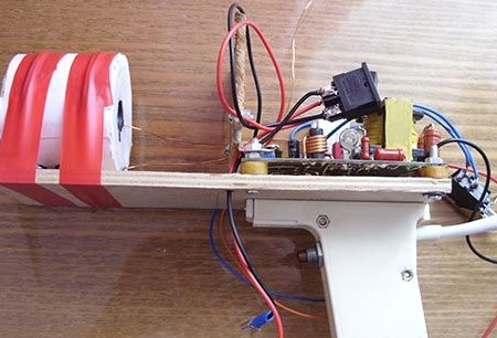
Install electronics and coil:
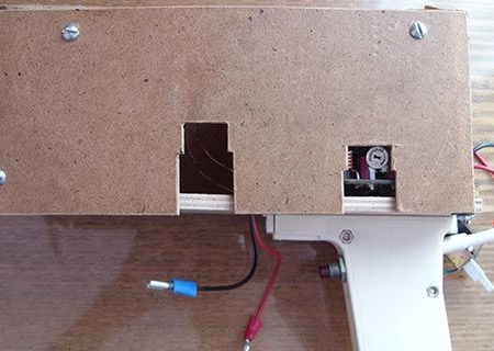
Install the shield:
Install the switches and battery:

Here are the gun shells:
Here is the finished gun:
