

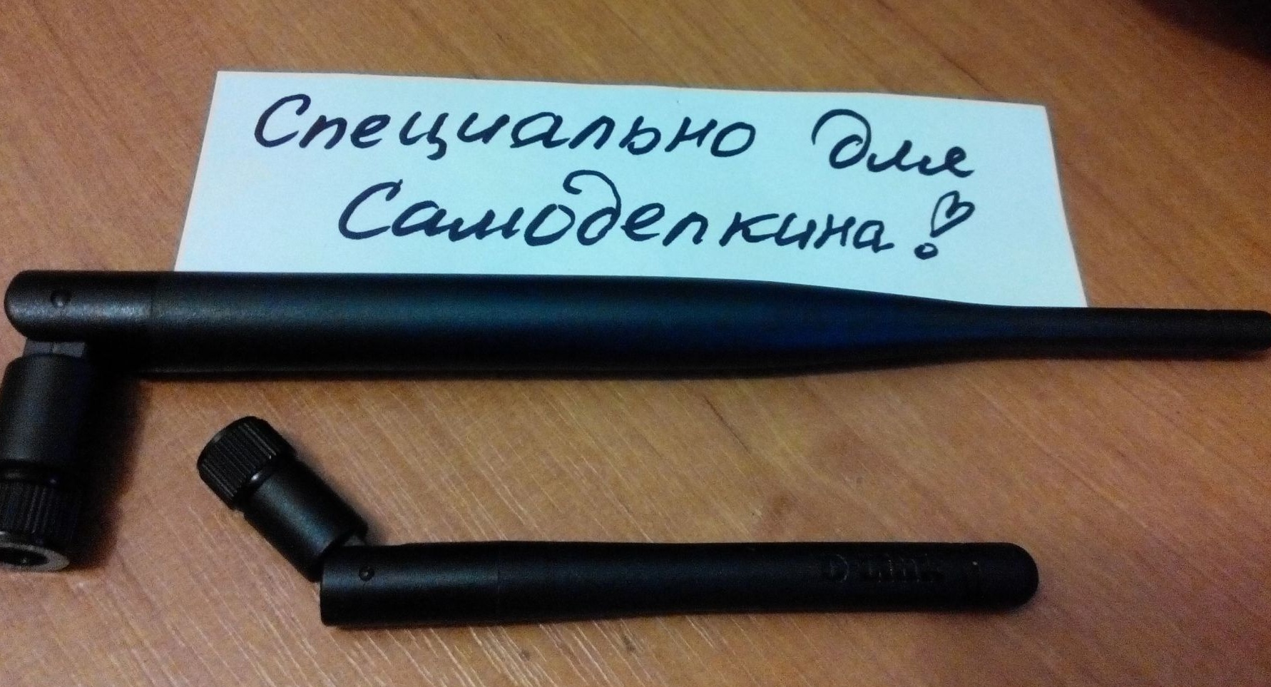
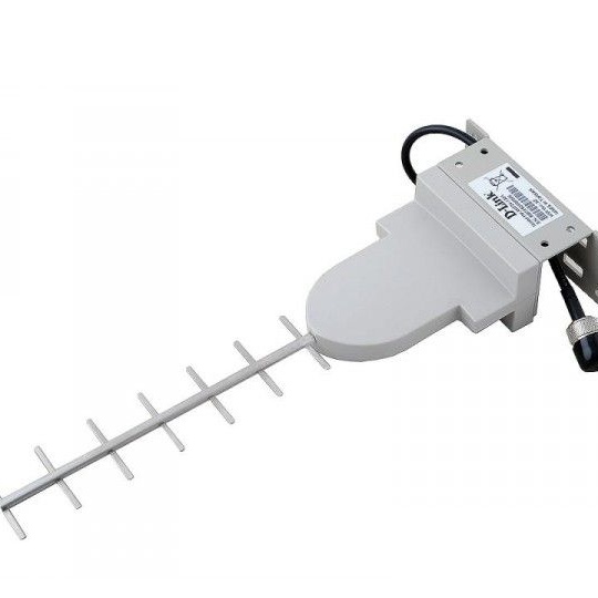
Now many cannot imagine themselves without the Internet, access points Wi-Fi networks. To increase the signal power of the transceivers, both standard and additional antennas are used. Power antennas range from 2 to 9 dBi, approximately. They look like this:
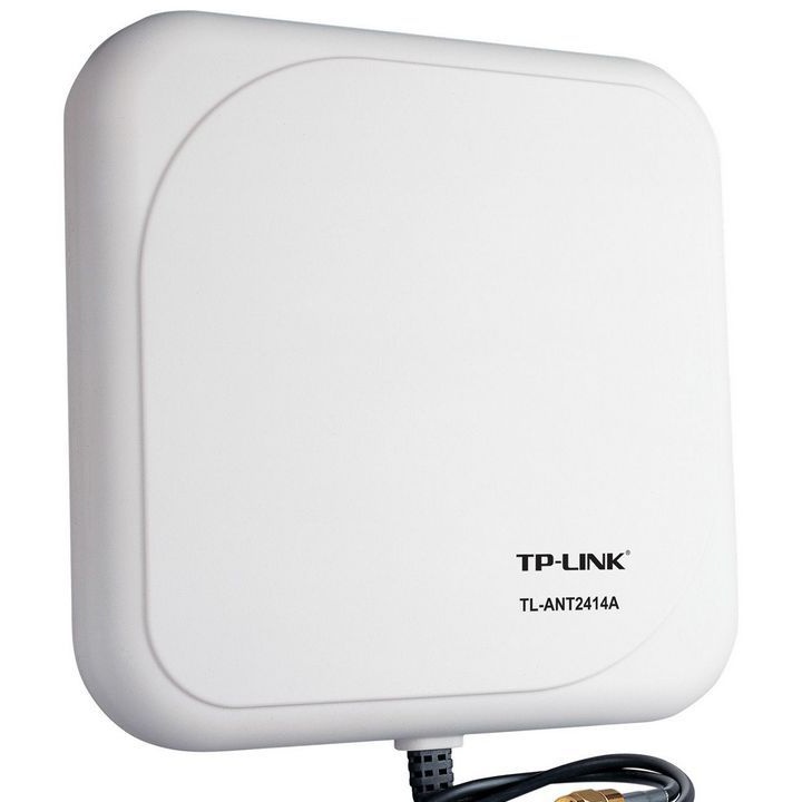
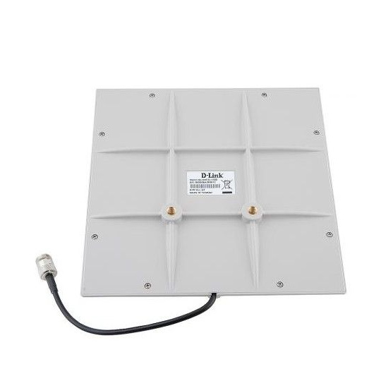
To increase the power and range of the directional signal, external antennas are used, which are installed outdoors and connected to a 50-Ohm cable receiving / transmitting device (not 75 Ohm !!!). They look like this:
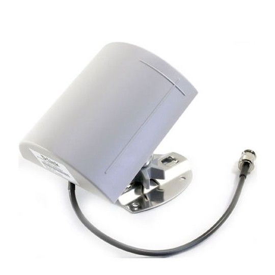
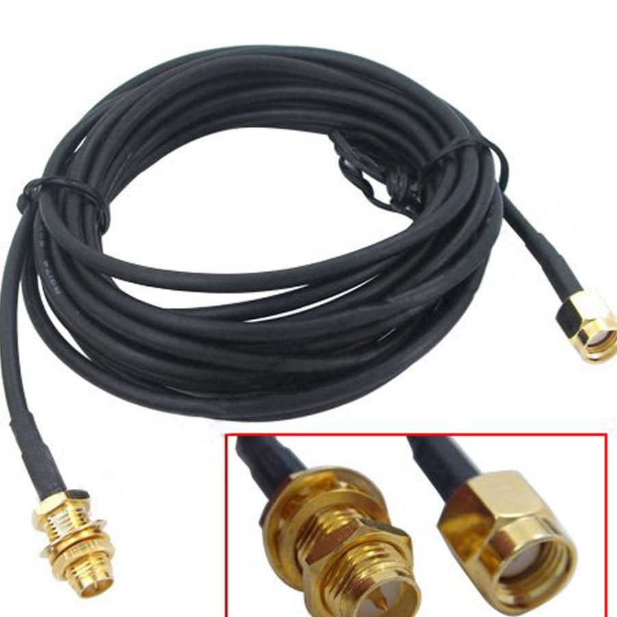
The connecting cable in addition to 50 Ohm resistance has specific terminals:
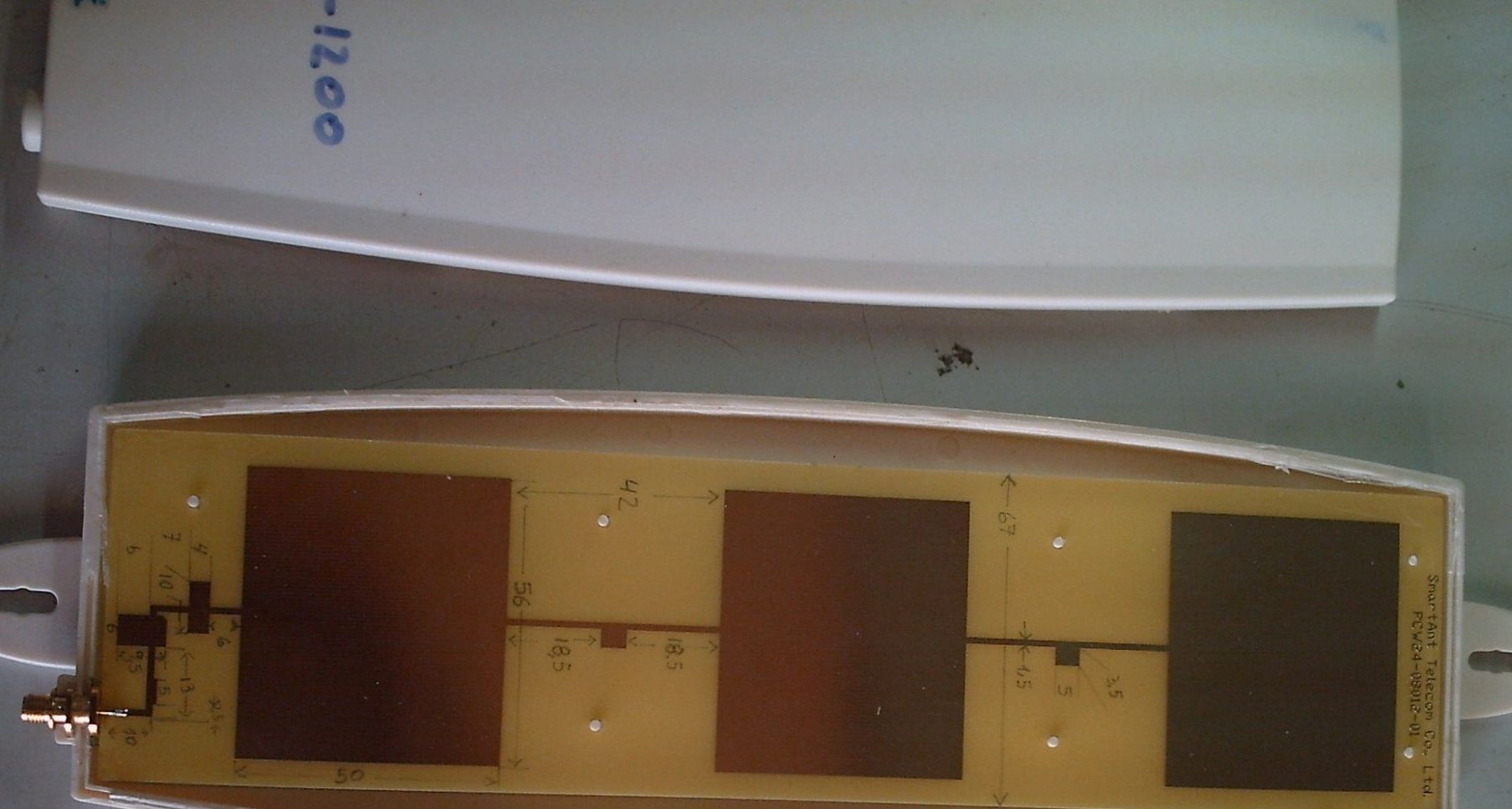
Cable and lugs are in stock at electronic stores. But the antennas themselves are oh oh how cheap. If you look at what is inside such an antenna, you will understand that it is not worth that money:
After watching and monitoring the Internet, I decided to do it myself.
So we need:
- foil fiberglass, single-sided, 1.5 - 2 mm thick, 220 to 230 mm in size;
- jigsaw, with a metal file;
- drill or screwdriver;
- fine sandpaper, drill bits for metal;
- spray varnish;
- metal sheet, dimensions 270 * 240, thickness 0.5-1 mm;
- ferric chloride solution and capacity (tray for example).
So stage one.
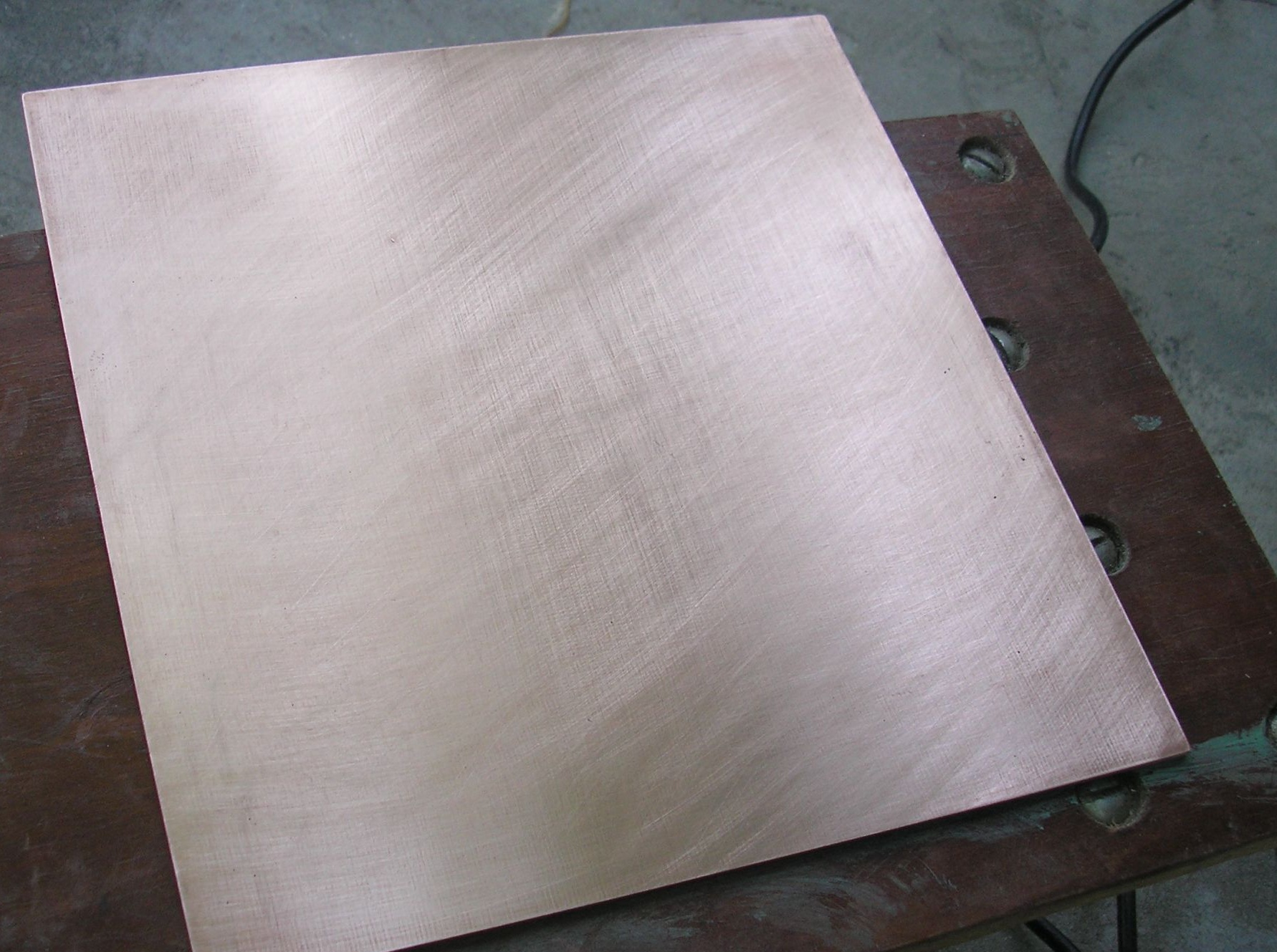
We mark and cut the fiberglass sheet according to our sizes. We process the edges and clean the surface of the copper side.
Next, the second stage:
We will need the services of an advertising or printing center, and specifically an organization that provides services for plotter cutting of self-adhesive film. Download the file, transfer the file to the USB flash drive - Antenna.rar (at the end of the article).
On the film you will be cut out the pattern of conductors and vibrators of our antenna. To transfer the film to the copper coating of the PCB, for convenience, ask either immediately stick on the cut or transport (advertising) film with you.
Stage three - sticking a pattern.
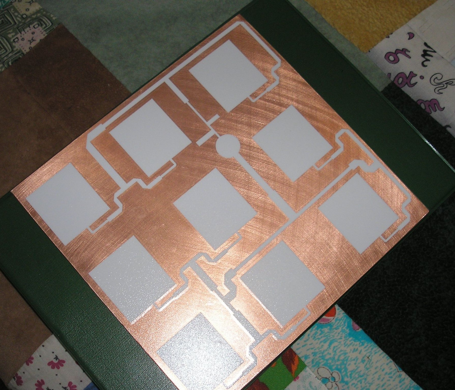
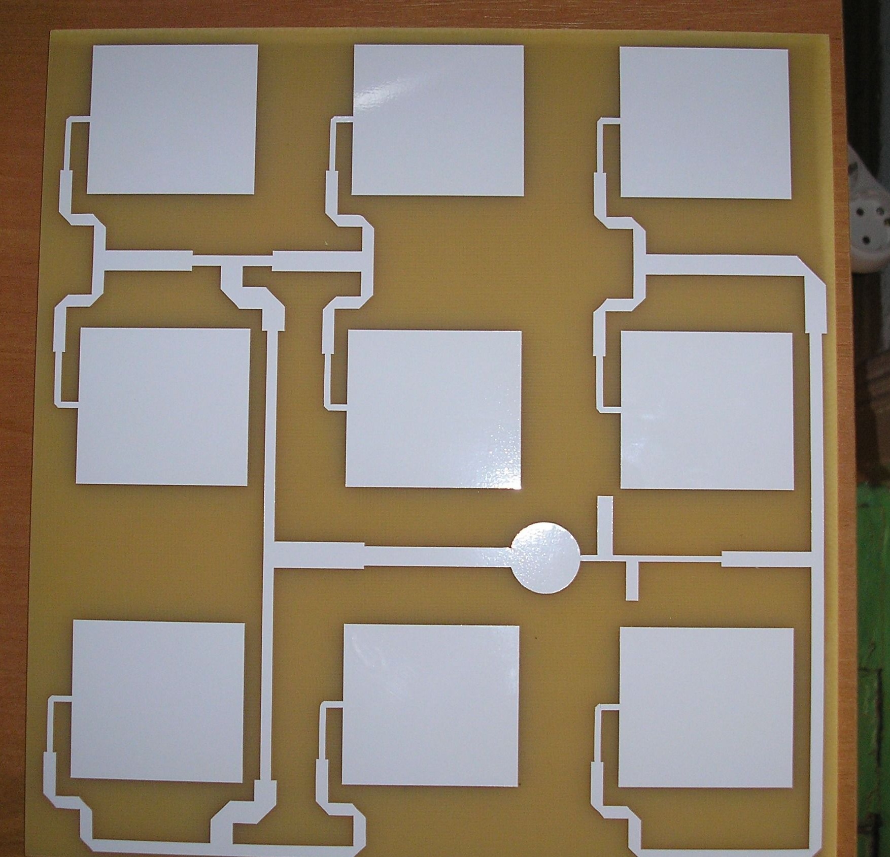
Before sticking the film on copper, it is necessary to degrease and allow to dry. Then we take it from the self-adhesive sheet, cut out our pattern at right angles (if they were printed a lot), apply an advertising film on it (if you did not put it on the company).Peel off the protective film and remove the unnecessary part of the pattern, background. We glue everything that remains on the copper part of the PCB, smoothing and preventing air bubbles from forming. It will turn out like this:
Stage Four.
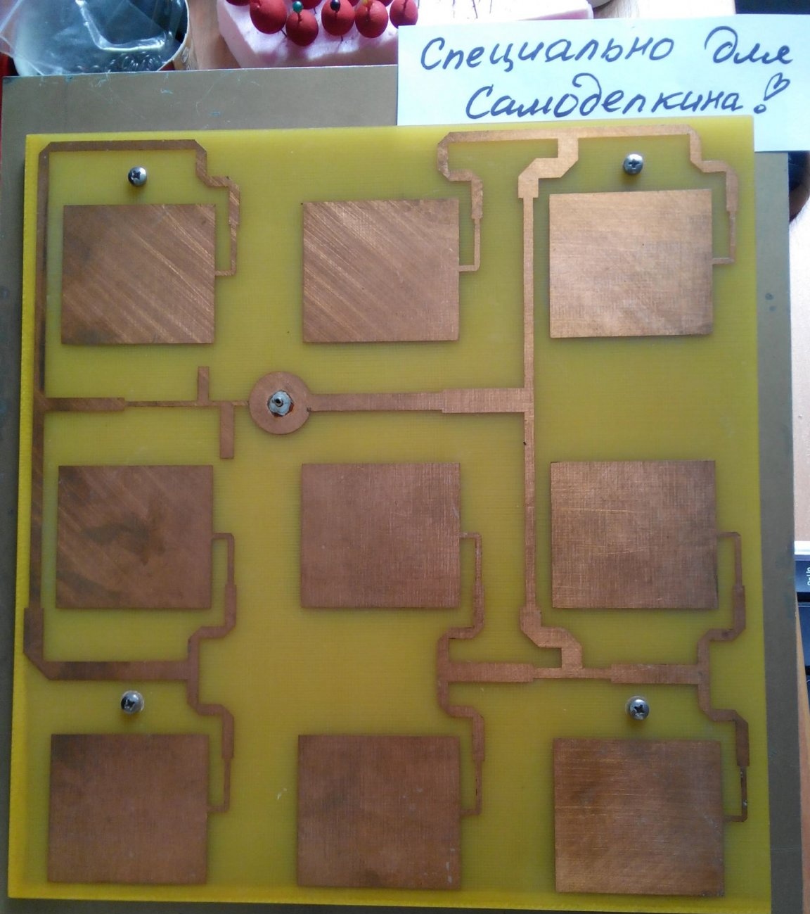
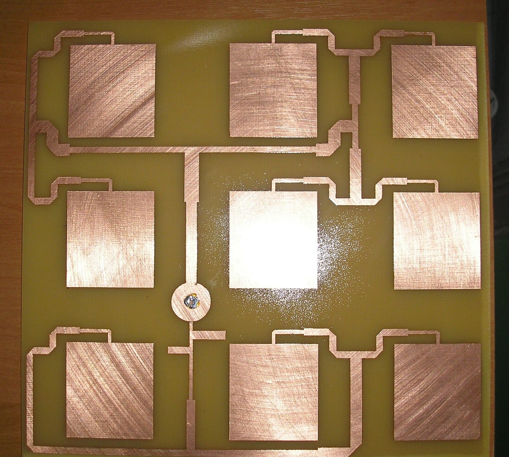
We prepare a container of a suitable size. We dilute ferric chloride, in a proportion of about 100 g per 0.5 liter of water, heated to 60-65 degrees Celsius. Dismantle the advertising film. We lower our design, fiberglass to the bottom of the tank. Periodically fidgeting the workpiece along the bottom of the tank, we wait for the end of the etching of the copper layer. At the end, we rinse under running water and wipe dry. It will turn out like this:
Remove self-adhesive. Next, in a round polygon, drill a hole for the central pin of the connector, for the cable. We take a spray can with varnish, open it in several layers with each drying. Then gently clean and tinny the soldering place.
Then, at the corners of the PCB and the metal plate, we drill four holes, for connection as a sandwich, but with a gap. The distance between the copper layer and the beginning of the metal layer is 5 mm.
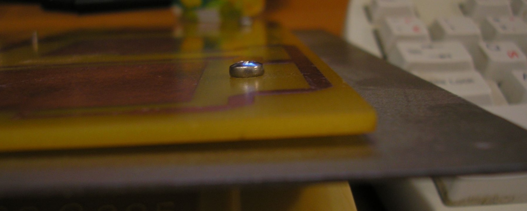
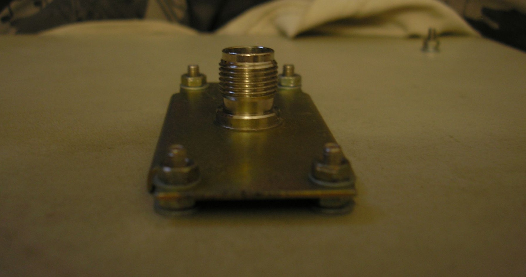
The connector was first fixed with a nut to the plate, and the plate to the screen surface.
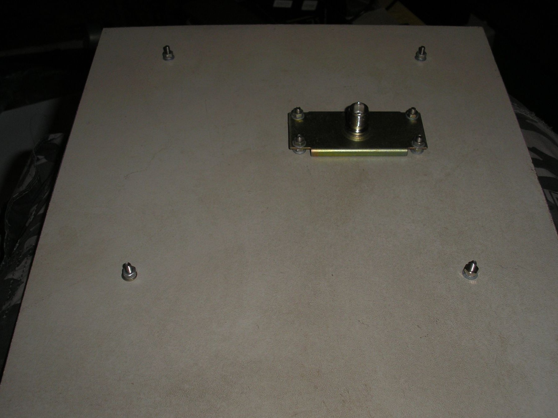
That's basically it, the cable is mounted without problems, or bought ready. The cable length is desirable so that it is minimal, from the antenna to the wi-fi device. The gain of this antenna is about 24 dBi. With good visibility between the objects of communication, the distance can be several kilometers.
Files: