

Nowadays, we are increasingly using devices powered by various batteries. Sealed helium batteries (6 and 12 V) are often used in uninterruptible power supplies and portable portable receivers with daylight bulbs. If you use these batteries separately in other devices, you need to charge them.
Faced with the problem of the charge of such elements, I looked up the search on the Internet, found a simple circuit, with a little correction of which an adjustable power supply was also introduced.
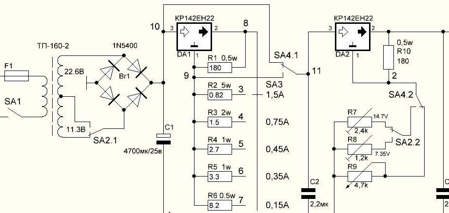
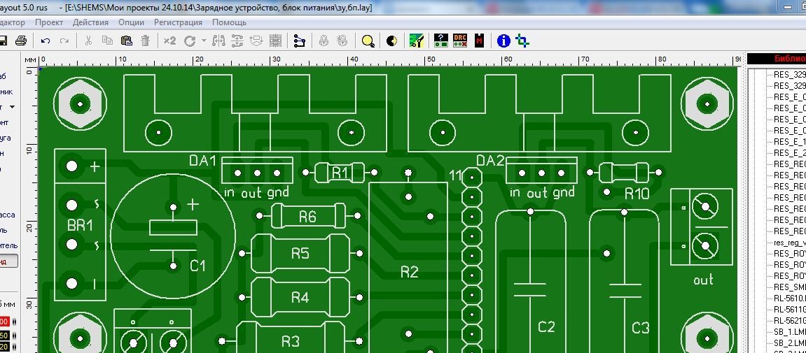
The circuit is duplicated on many sites, the source can not be found for sure, but not a circuit board can be found on any site. Having spent some time, I drew a printed circuit board, in the form of a modular block, in the program Sprint-Layout 5.0 (6.0).
The proposed combined charger has the following characteristics:
- charging batteries with a voltage of 6V;
- charging batteries with a voltage of 12V;
- setting the charging current, five fixed values: 0.15; 0.35; 0.45; 0.75; 1.5A;
- an adjustable power supply, voltage from 1.2 to 28V, with a maximum load current of 1.5A.
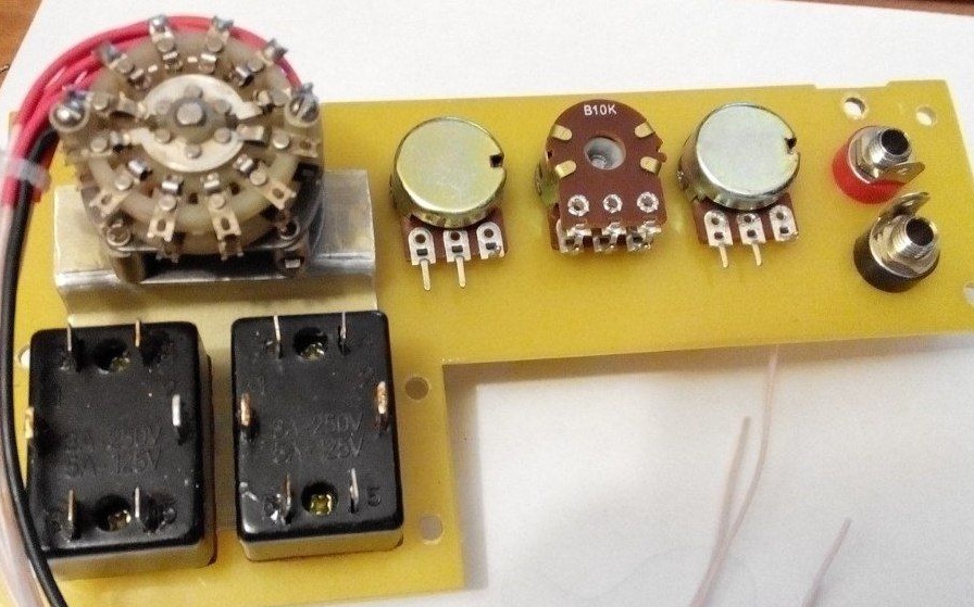
The circuit is simple, but during installation it is easy to get confused in the wiring of variable resistors and toggle switches. Considering this moment, the wiring diagram was also drawn.
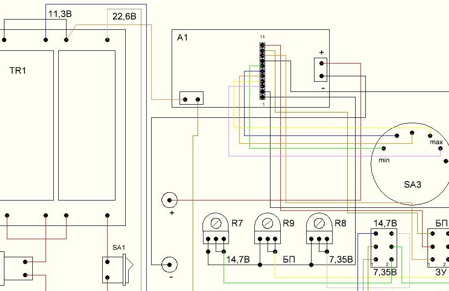
On the wiring diagram, variable resistors and toggle switches are located facing you.
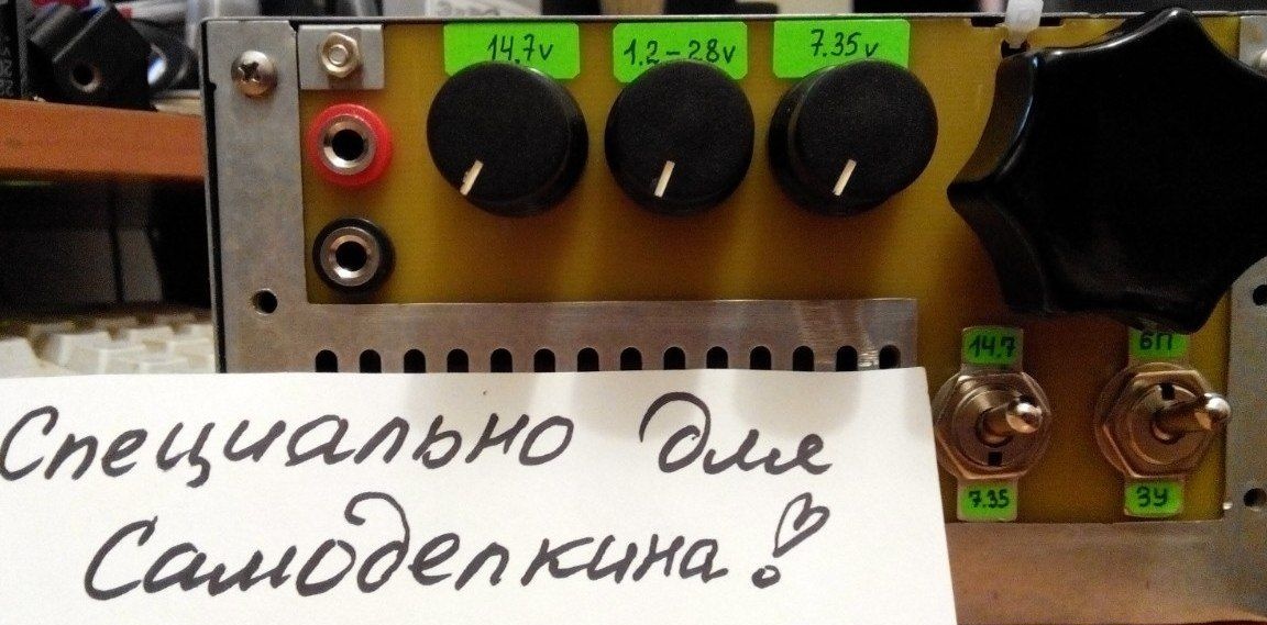
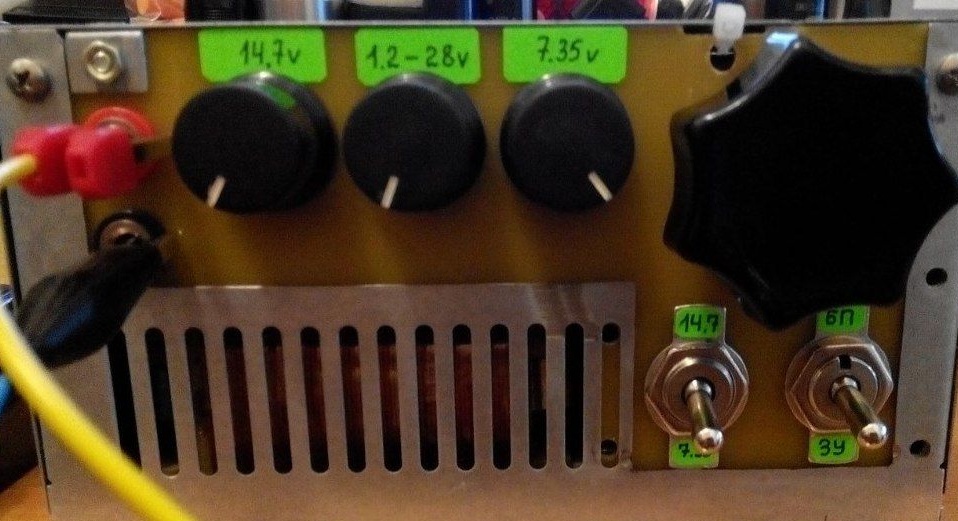
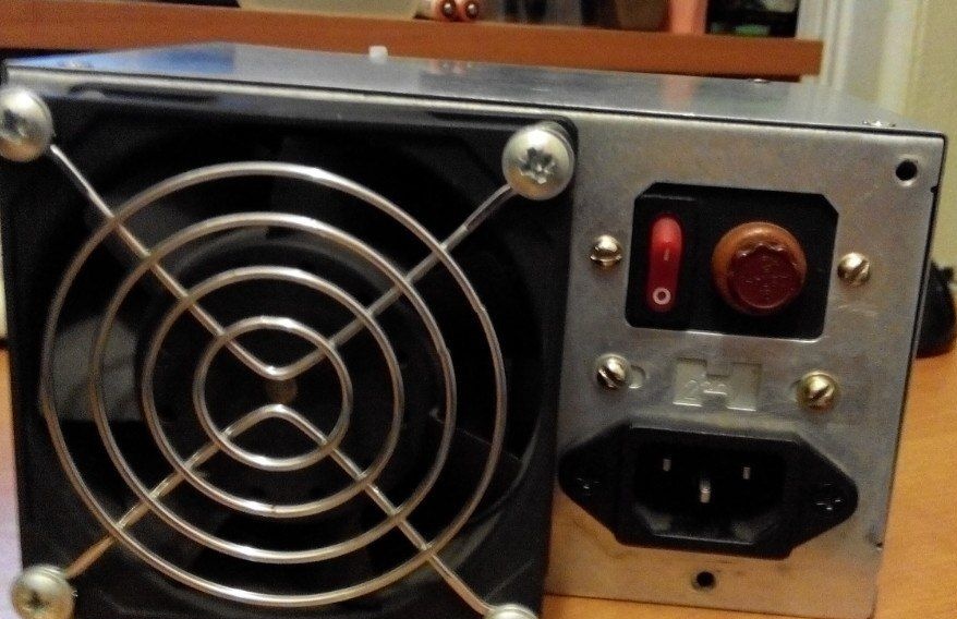
As the case, the case was used from a computer power supply unit of the form of the AT factor (truncated), with a slight alteration, namely cutting out a part of the case and installing a fiberglass insert instead.
On the panel are installed: variable resistors R7 - R9, toggle switches SA2, SA4, five-position biscuit switch current mode, output connectors.
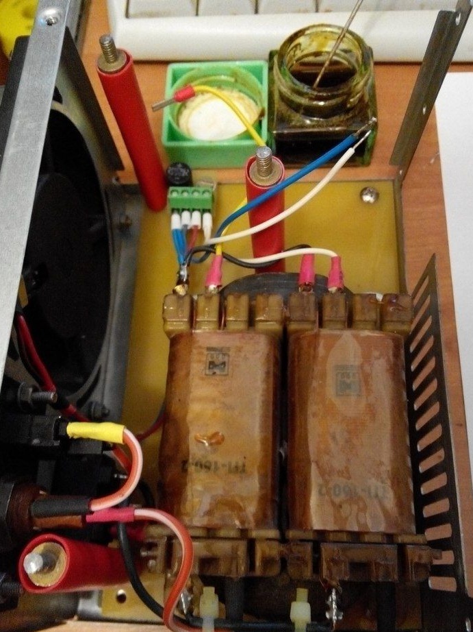
Additionally, a cooling cooler with a diode bridge is connected to one of the transformer arms.
Unfortunately, there is no photo of the assembled module, because it is already mounted inside the case. Here is a screenshot of the circuit board drawing:
Details
The TP-160-2 power transformer used in my version can be replaced by any with the same parameters, two secondary windings of 12v each and a load capacity of at least 1.5A.
The printed circuit board is made of 1.5mm thick foil fiberglass. Variable resistors of linear characteristic. An analog of the kr142en22 chip is LT1083. The remaining elements and their characteristics are shown in the diagram.
Photo of the finished device.
A little bit about the operation.
As a result of the first launch, the expectations were met, everything worked. When using a 6V battery in charge mode, it is necessary to set the charge voltage to 7.34V (adjustment from 1.2 to about 8V), 12V battery set the charge voltage to 14.7V (adjustment from 1.2V to about 18V). The charging current is set depending on the capacity of the battery, according to normal, not more than 10% of it.
The schematic and wiring diagram attached to the article are made in SPlan 7.0, there are two tabs in the file.
Files: