
Previously, I already had attempts to make a homemade wind generator, but then it was just experiments to understand and see how it all works. First crafts were in 2001 and 2002, but then this topic was safely abandoned, and all the details from the wind generators were lost or sold over time.
Now I wanted to make a better and more reliable wind generator from improvised materials. I did not need a lot of power and a lot of energy. But I wanted to have a reliable wind generator so that in a normal wind it would stably generate 30-40 watts / h of electricity.
I saved 10 coils from old wind generators, about 60 turns of 1.5 mm wire are wound there. I decided to use these coils for this generator. After a short search for cheap magnets, they managed to get them for only $ 1.5 apiece, in the amount of 20pcs. The generator will be single-phase, 10 coils and for each coil two magnets on the rotor disks.
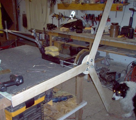
The manufacture of a wind generator began with a frame, the basis of a wind generator, so to speak. The windmill decided to do like everything according to the classical scheme with a folding tail. I found pieces of a profile pipe from which I welded the frame with the displacement of the wind head relative to the rotary axis. From the old trailer I found the hub that I used. I drilled a hole and inserted the axis shaft, then welded on both sides.
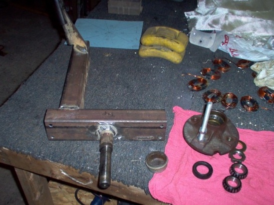
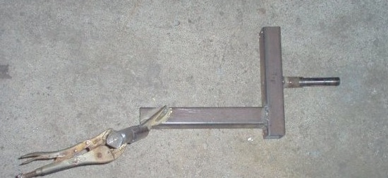
Further on the photo you can see how the mount was made for the tail and how much the axis of rotation of the generator is offset from the center. The axis of the generator is not welded quite horizontally. I lifted her up a little, about 2-3 degrees, so that the blades were away from the mast, because with a strong wind they bend very much and can beat on the mast.
The tail pin is welded at an angle of 45 degrees relative to the axis of rotation of the screw, the vertical deviation of 20 degrees. Then the finished tail is simply worn on this pin. When the wind generator is in the wind, the tail looks to the side, since the axis of rotation of the screw is offset from the center, thus achieving balance, but if the wind became stronger, the screw goes to the side and the tail folds. It is usually difficult to accurately calculate the tail, it is better to adjust it later to the desired wind depending on when it begins to take shape. The tail area should be 20% of the swept area of the screw.
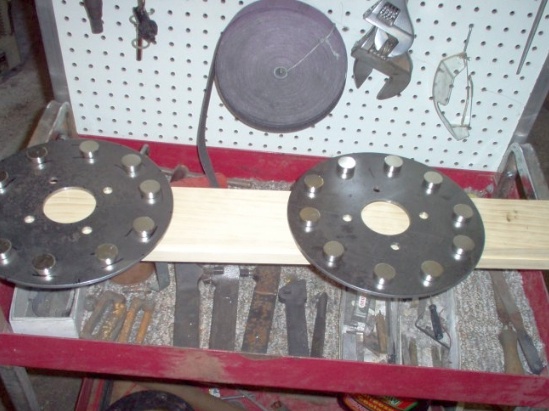
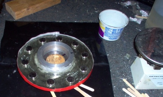
Further, two disks of the future rotor for magnets were machined from metal.For the disks, I cut out two octagonal blanks, which I took to my friends and they turned two of them on a lathe to me. Then, holes for mounting were marked and drilled on the disks.
The stator was also manufactured according to the scheme worked out by all. A blank is cut out of plywood, then coils are placed and soldered together. If you are doing a single-phase generator like me, then the coils are connected together, the end of the first with the end of the second coil, and the beginning of the second with the beginning of the third, and the end of the third with the end of the fourth, etc. If you mix the connection of the coils, the generator will not work. For three-phase coils in phases are connected in one direction, that is, all coils of each of the three phases end with the beginning.
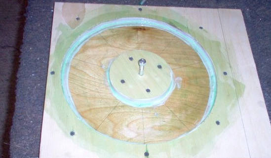
Here is my blank for filling the stator, joints and the whole form I missed with PVA glue, it was just nothing else at hand. It is better to lubricate the mold with petroleum jelly, grease, wax, for example, in general so that it will not allow the polyester resin to stick to the mold, otherwise it will then be difficult to pick out the stator from the mold.
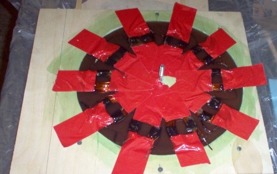
So that the coils couldn’t move, I fastened them to red tape, then gently poured the prepared resin and pulled the lid on top, which I had left after cutting the circle in plywood under the stator.
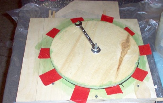
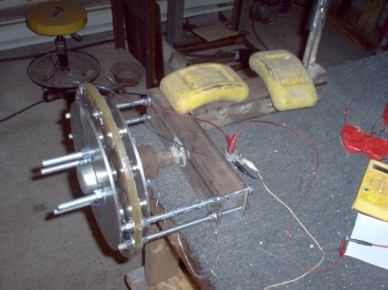
As the resin completely hardened, I removed the stator and immediately decided to assemble the generator and check what happened. At first I twisted my hands without a diode bridge, I managed to spin the generator up to 15 volts with my hands. Autumn pleased the result, then it assembled a diode bridge and already made measurements using direct current. From hand to 15 volts, the same, short-circuit current from hand to 5A, the generator is very resistant, but the result exceeded all expectations and was more powerful.
I tried to twist my hands and charge the battery, I managed to get a charging current of up to 1.1A, this is somewhere at 300 rpm, which means that there will be much more in the wind, as the screw should easily spin up to 1000 rpm with good wind.
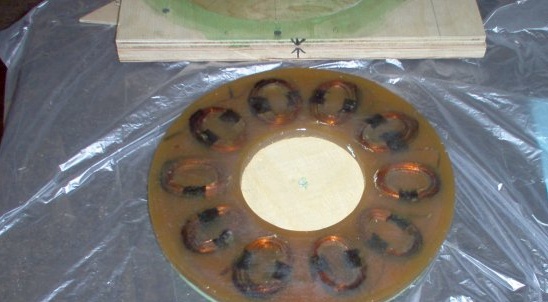
So as to prevent the magnets from flying off the discs, I also filled them, but with epoxy. To ensure good adhesion of the resin to the metal, the discs were once again smoothed out. The magnets on the disks must alternate between the poles, and the two disks must be attracted, that is, the magnets on the disks must be opposite poles against each other and attracted.
He made blades from a pine board, and decided to make high-speed blades this time. Previously, I made and put on my windmills many blades with large angles relative to the wind. They got great torque, but very low revs. Now I have made three blades with an angle of only 3 degrees. They have a low starting moment, but it is not important since the generator has no sticks and starts to rotate easily. But the blades have a great speed, which means that the generator will spin at high speeds.
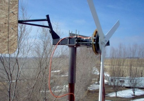
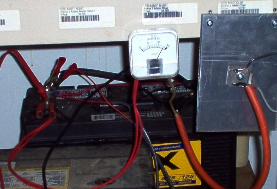
Here the wind generator is finally assembled and installed on the mast. As you can see in the photo, the pipe is dressed on the pipe, this is the easiest option. The wire ran outside without any tokosemnyh rings. Then let him inside the pipe. After installation, I immediately connected the wind generator directly to the battery through an ammeter. The wind on this day was small and the charging current reached 5A. But then the wind became stronger and the current sometimes exceeded 10A.
I found a new ammeter with a scale up to 30A, in strong gusts of wind the arrow deviated almost to the end. Below, the moment when the charging current was 28A is just recorded. The current can be much greater, but protection from strong winds is triggered and the screw is turned away from it and resets power and speed.
The structure is strong and protection can be made to operate on stronger winds, but the wire of the coils is thin and will get very hot, so it’s better not to do this so that the stator does not overheat and the varnish in the coils and the resin melt.