
Pultoids are called such robots that can be controlled remotely using the remote control. For example, a TV remote control may be used for these purposes. The main task that the author set himself in the manufacture of such a robot is the simplicity of its assembly. Considered robot does not require the manufacture of a printed circuit board, installation is very simple and just happens on cardboard.
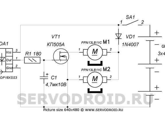
Electronic The robot circuit consists of only four components: a diode, a transistor, a photodetector and a capacitor. For the manufacture of the mechanical part, a minimum of materials will also be needed, for example, a CD-ROM is used to make the case.
A robot made in this way will understand only one team. It is worth pressing any button on the control panel and the robot will begin to turn. If you continue to hold the button, the rotation angle will become larger, as a result, the robot can turn 360 degrees.
Robot device
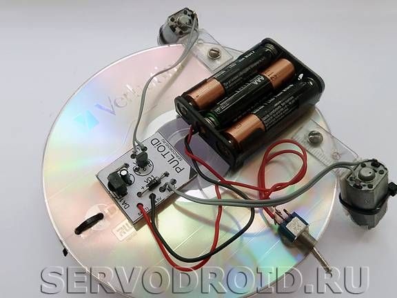
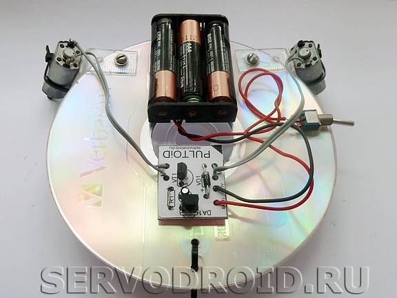
A compact disk is used as the basis for the manufacture of the robot. As for the power elements, they are attached using M2 bolts. The electronic board, also the battery compartment, is attached using tape.
Now about the engines, they are located at an angle and their shafts rest against the road. Thus, there is no need to separately manufacture the wheels. Bolts are fastened using frames that are made of a school line.
Three “little finger” batteries feed the robot, they are installed in a special case. In total, the power supply produces 4.5 V.
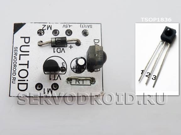
And finally, the photodetector, it is only one here, it is a type of TSOP. It receives modulated signals from any remote control, thanks to which the robot can be controlled.
Materials and tools for manufacturing:
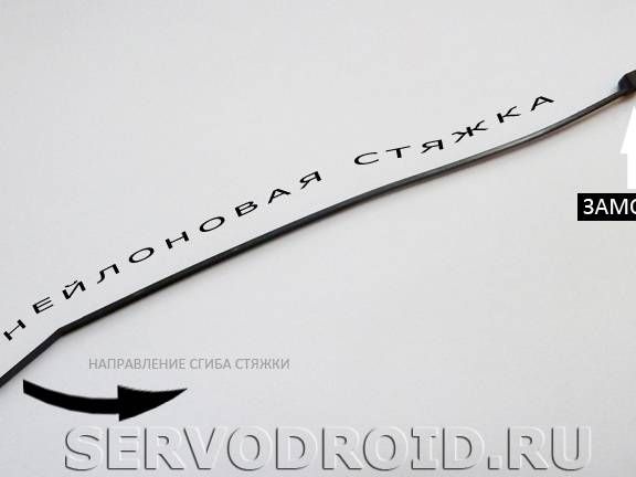
- nylon ties;
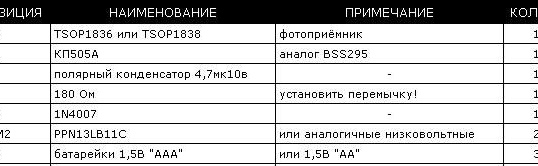
- photodetector type TSOP1836;
- one field effect transistor (KP505A);
- compact disc;
- fular for batteries in three sections;
- three "little" batteries;
- plastic ruler;
- screws for attaching the frame;
- wires and switch (cross over type).
Manufacturing process:
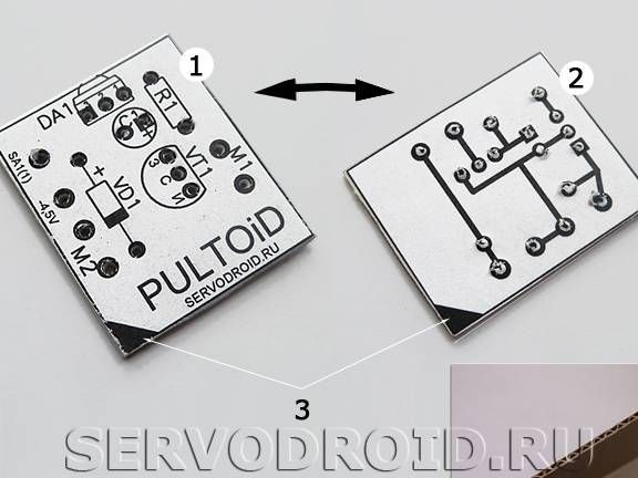
Step one. PCB design
To make a printed circuit board, you first need to print a drawing on paper. You should get two pictures, on one installation drawing, and on the other side of the board. In total, the board will consist of three elements, in the center there will be a corrugated cardboard glued with office paper on both sides. To glue the board, it is recommended to use a dry glue stick.
Step Two Installation of radio components
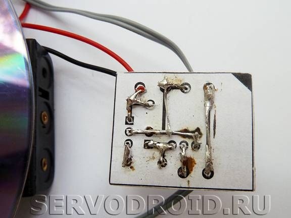
When installing electronic components, it is important not to forget or cut off the protruding edges of the contacts. Subsequently, they will be bent, and thus an electrical circuit will be created. All elements are connected by soldering according to the specified scheme.
Resistor R1 in the circuit must be replaced with any jumper. As for the photodetector, the correct order of its connection is also shown in the photo.
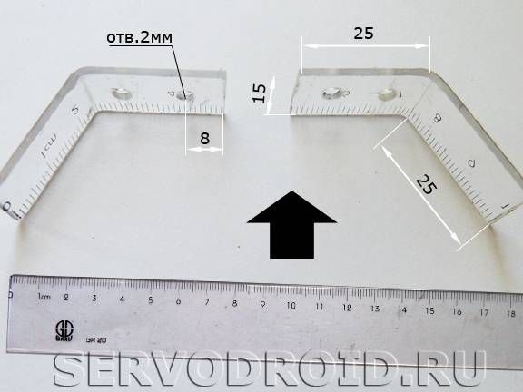
Step Three Power Frame Installation
To install the engines, you will need to create a power frame. As a material, a plastic school ruler will be used here. It must be cut into two parts and bent as indicated in the photo. To make the ruler begin to bend, you need to bring the hot soldering iron tip to a distance of about 2 mm to the place of deflection. Also for these purposes, you can use a construction hairdryer. The ruler needs to be smoothly bent to an angle of about 30 degrees.
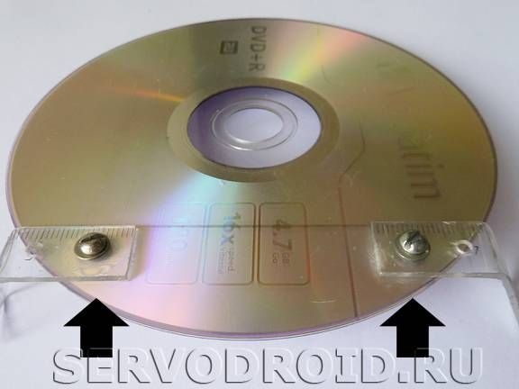
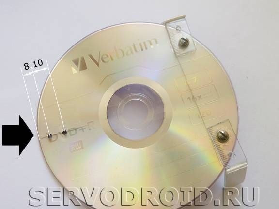
After the frame is created, you can proceed with its installation. To do this, take the CD and 2 mm screws with nuts. Further, holes of at least two millimeters in diameter are drilled in the right places, and the frame is fastened with screws. So that the frame does not slip, before installing it you need to stick double-sided tape on the disk.
Step Four Installing the front support
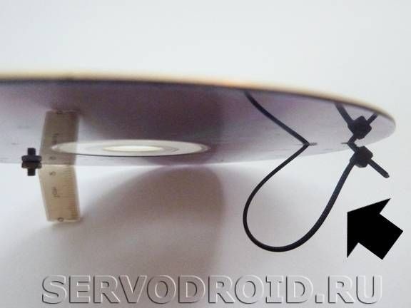
In the front of the disc, you need to drill two holes and prepare a nylon screed. The screed size should be 3x150mm. It must be inserted as indicated in the photo. As a result, the resulting support will depreciate perfectly when the robot is working and glides along the road.
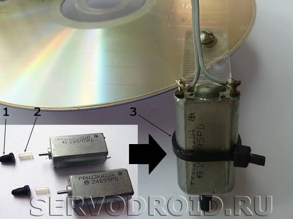
Step Five Engine installation
In order to prevent motor shafts from sliding along the road, protectors must be put on them. They are made from gum, which can be found on the pastes of helium pens. To install the engines, you first need to glue a piece of double-sided tape to the support, it will prevent slipping. Well, then the engines are finally fixed with nylon ties.
Step Six Switch and power supply connection
As a power source, you can use any battery whose current does not exceed 5 volts. In this case, a case is used for three finger batteries, which total 4.5 V.
As for the switch, it is mounted on the gap of the positive contact coming from the power source. The red wire is attached to the board to pin SA1 (1), and the black wire to pin -4.5V.
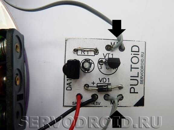
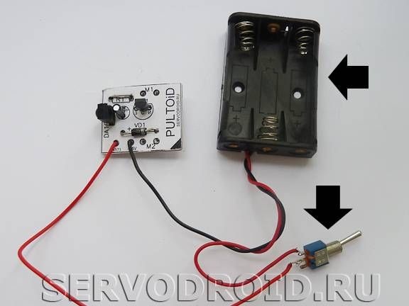
Also at this stage, you can connect the motors, their wires are connected to the contacts M1 and M2.
Seventh step. The final stage
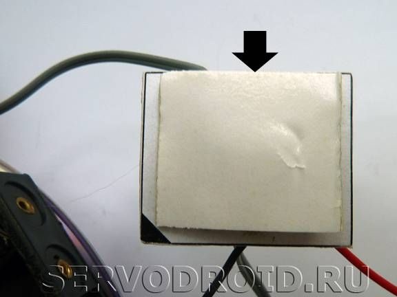
At the final stage, all electronic elements need to be fixed. They are attached to the disk using double-sided tape. As for the switch, it also needs to be fixed, for this you can use hot glue.
That's all, now the robot is ready. You can try to turn it on and give a command to turn using any remote control.