
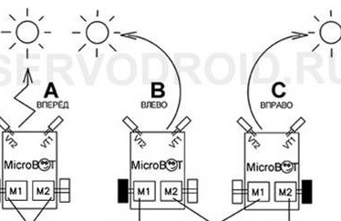
Robot Microbot is a simple little robot that can be made do it yourself. Its height is about 12 mm, width is 20 mm, and the length of the printed circuit board is only 35 mm. The peculiarity of such a robot is that it can move behind a light source. Once the robot shines a flashlight in front of it, it immediately begins to move towards the light, which is somewhat reminiscent of a laser pointer game with a cat. The robot also reacts to the sun's rays, so it can be difficult to imagine how it will behave. The robot moves only on a flat smooth surface.
As the “muscles" the robot uses miniature motors, which can be found in old mobile phones.
Robot device and functions:
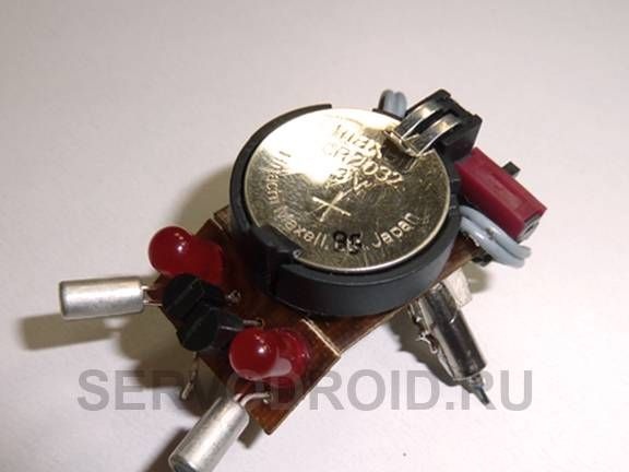
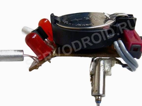
In technical terms, the robot consists of two printed circuit boards of different sizes. The boards are connected using solder. On the surface, the robot is held by three points of support, while two points of support are the motor shafts, they move the robot. Since the dimensions of the robot are small, a flat battery with 3V power is used as power here.
Light the robot feels very much. The robot perfectly catches not only the direct hit of light on it, but also sees the light that comes from the light spot.
The robot has two LEDs. If you shine on the right side of homemade, the robot starts to move to the right and the right LED on it lights up. Accordingly, if you shine on the left side, the left LED lights up and the robot goes to the left.
Materials and tools:
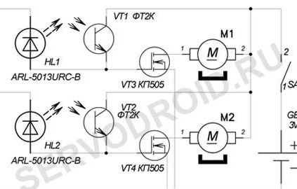
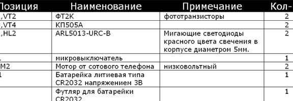
- phototransistors type FT-2K;
- blinking LEDs ARL5013-URC-B;
- one field-effect transistor KP505A;
- 3V lithium battery type CR2032;
- case for horizontal installation;
- microswitch;
- two motors from mobile phones.
Manufacturing process:
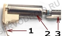
Step one. We get motors
The necessary motors can be found in old mobile phones. They are needed here in order to create vibrations, eccentrics are put on their shafts. The most crucial moment here is to correctly remove the cam. If you tighten it with pliers or in another similar way, the motor will become worthless. In order to remove the eccentric, it must be clamped in a vice or taken with pliers. Next, an awl or a large needle is taken and with it you need to knock the shaft out of the eccentric. Care must be taken, as it is easy to damage the contacts or the motor housing.
Step Two PCB design
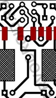
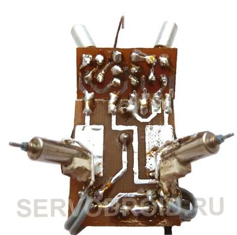
In the figure you can see the drawing, what should be the printed circuit board.In the manufacture of the board there is one point, we are talking about a thin vertical line that separates the board. When manufacturing a board using the LUT method or etching, it must be manufactured as a single unit.
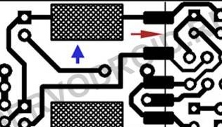
After the necessary holes are drilled in the board, it can be cut in a vertical line, which is indicated by the red arrow. The result should be two small printed circuit boards. As for the big one, it has a case, a microswitch and motors on it. On the second board, the smaller one installs radio components, these are phototransistors, LEDs and field effect transistors.
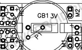
Particular attention should be paid to the time of installation of phototransistors. They need to be installed in such a way that the length of the terminals is about 15 mm, and then bend in different directions by 30-35 degrees. As for the jumper P1, it can be replaced with any piece of wire. The jumper must be made before the case is installed, otherwise after that its installation will be impossible.
Another point concerns the switch, it has three outputs. Its central output is closed, depending on how the slider handle is located, it is either a right or left contact. Only two outputs will be used in the circuit, this is the central one and any side one. In order for the switch to fall into place as expected, one of its contacts must be cut off. Or you can use a different microswitch of small sizes.
Step Three Engine installation
Engines are installed on the site from the side of live tracks. To fix the motors, the author used paper clips. It needs to be bent in the form of the letter P and then tin in the necessary places. Subsequently, the clip is soldered to the site for mounting the engine.
Solder the paper clip to the engine as quickly as possible, otherwise the motor may overheat and fail. Soldering is best done with pliers. Next, the motors are allowed to cool and the paper clips are bent as needed.
After the motors are installed, they will remain connected. For this, the wires are connected to the terminals of the M1 and M2 boards. It is best to use thin stranded wires for connection.
In conclusion, both boards are interconnected. The small board is placed at an angle to the larger and then soldered. In this case, you must be extremely careful not to short-circuit the contacts.
Step Four The final stage
Now you need to create a third fulcrum for the robot. For these purposes, the author used the contact from the capacitor. The height of the legs must be selected individually, the center of mass depends on it, and as a result, the entire work of the robot. The speed of the robot can be adjusted by changing the angle of the motors.
That's all, the robot is ready. Now you can insert a fresh battery, and enjoy the work of homemade.