
The peculiarity of the BIBOT-1 robot is that it can perform two tasks. It can move behind a light source or along a black line that can be drawn on paper. Robot very flexible in settings, that is, later it can be customized to any desired conditions, that is, to make it more sensitive to light or less. It is also possible to adjust the speed of rotation of the engines, this will allow the robot to work better, especially when moving along the line.
The device and the principle of the robot:
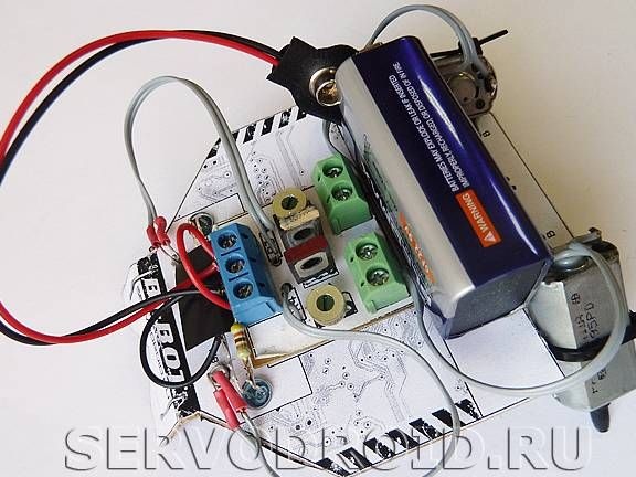
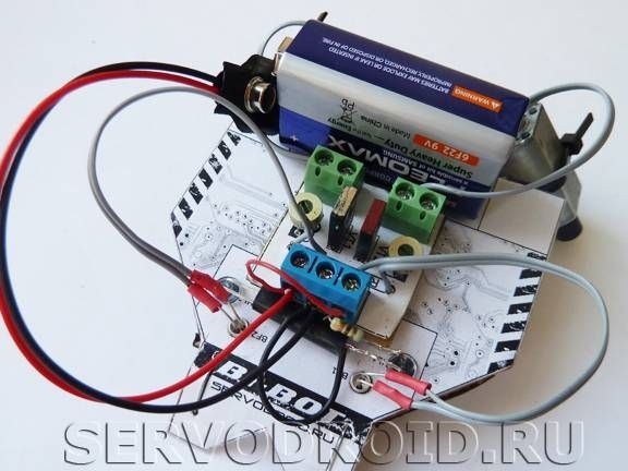
The base of the robot is made of cardboard, while the template is printed on the printer, and then crashes. As for the radio components module, textolite was taken as its basis, the module is attached to the base of the robot. To make the body stiffer, special ribs are used in the design.
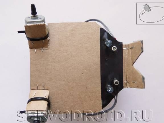
Engines are installed as in most of these homemade, that is, at an angle. Due to this there is no need to put the wheels and gearbox. To prevent the shafts from sliding over the surface, protectors are put on them.
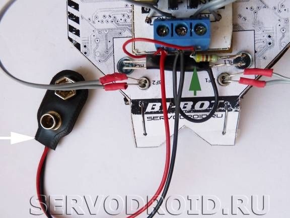
A 9V type 6F22 battery is used as a power source. The battery is attached with tape and is always available for easy replacement.
As for the switch, then auto decided to avoid installing it. The robot turns on and off by manipulating the clip that attaches to the battery.
And finally, the adjustment of the robot. To adjust the sensitivity of the robot, the system has two adjustment resistors. When they rotate, you can adjust the sensitivity of the robot to light, and you can also adjust the speed of rotation of the engines. The more sensitive the robot is to light, the faster it will move, and vice versa.
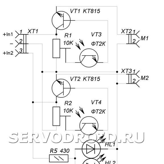
As for the principle of operation, everything is set out in the diagram.
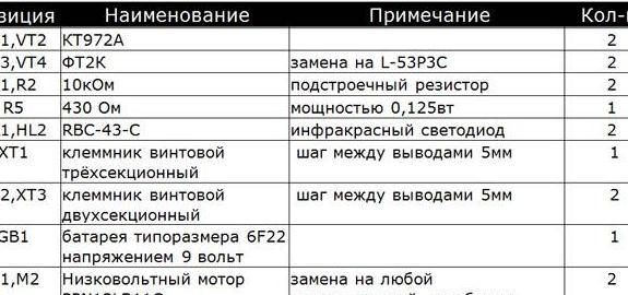
Materials and tools:
- 9V battery and clip for connection;
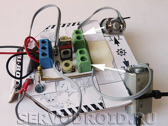
- two connectors for connecting motors (two-section terminal blocks);
- motors;
- nylon screed;
- protector (rubber roller);
- two phototransistors;
- two infrared LEDs;
- a bracket from a stapler;
- three section terminal block for power supply connection;
- tuning resistor.
Manufacturing process:
Step one. PCB design
The fee is created by the LUT method. Before work, the surface of the fiberglass must be thoroughly cleaned, and then washed and thoroughly dried. After manufacturing, the conductive tracks must be checked with a multimeter for a short circuit.
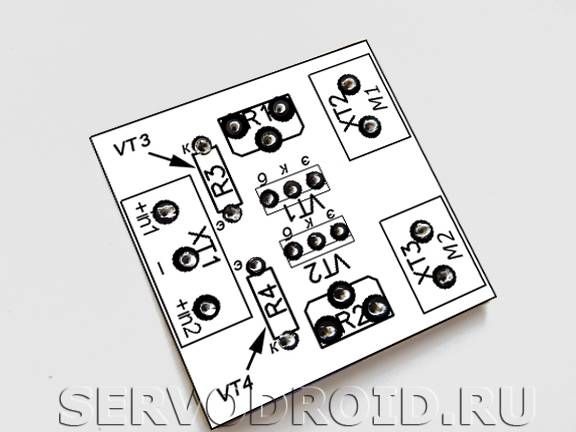
Step Two Installation electronic elements
Next, you need to take a drawing printed on paper and stick it to the created board. In this case, the holes on the paper and in the PCB must exactly match. Next, the radio components are installed as indicated in the diagram. In the process of work, the installation of resistors R3, R4 needs to install phototransistors VT3, VT4.
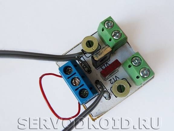
The extreme sections of the three-section terminal block XT1 must be connected with a mounting wire. The connection points of the contacts need to be well insulated, it is best to use a heat shrink tube for these purposes.
Step Three How to create a case
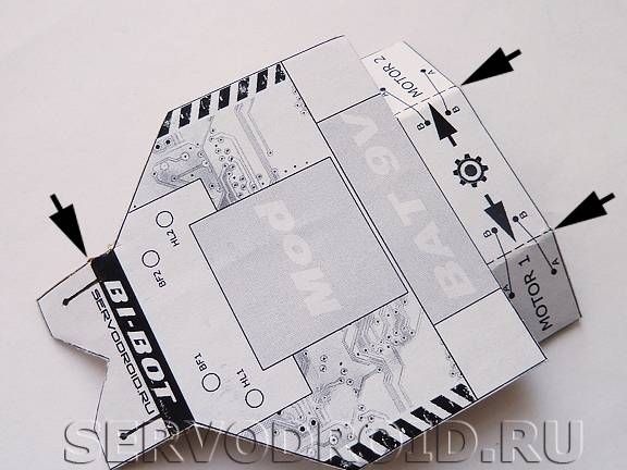
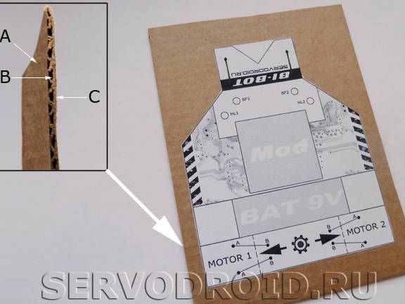
A drawing of the body must be printed on a regular sheet of A4 paper. Next, you need to take a piece of corrugated cardboard and stick a drawing on it, subsequently the case must be cut around the perimeter.
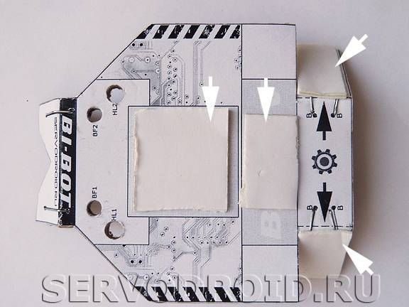
Where the "scissors" pictogram is located along bold lines, cuts should be made. Subsequently, along the black dotted lines, you need to bend the cardboard as in the photo and put the black arrows.
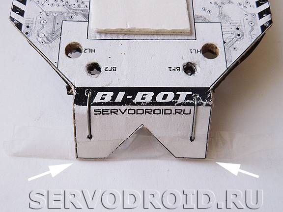
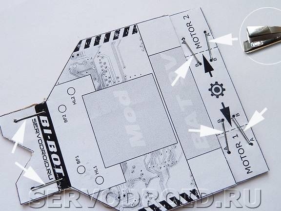
Front and rear of the housing to the specified position using a stapler, you need to install the brackets. Places of their installation are marked by black lines with circles. Staples are needed to make the frame stiffer. After installing the brackets, they are tedious to bend along the fold lines.
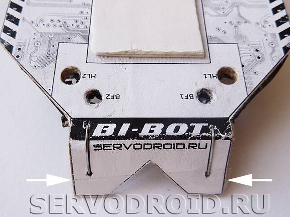
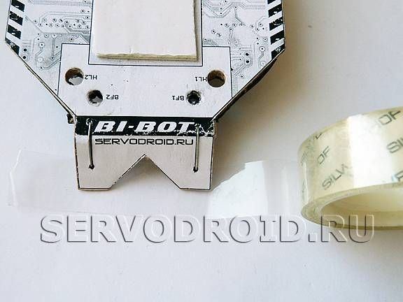
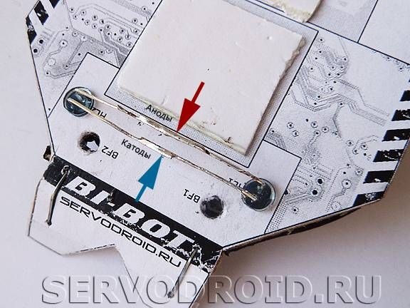
In the places marked BF1, BF2, you need to make holes for the installation of phototransistors. In places HL1, HL2, you need to make holes of such a size that they fit the diameter of the casing of infrared LEDs.
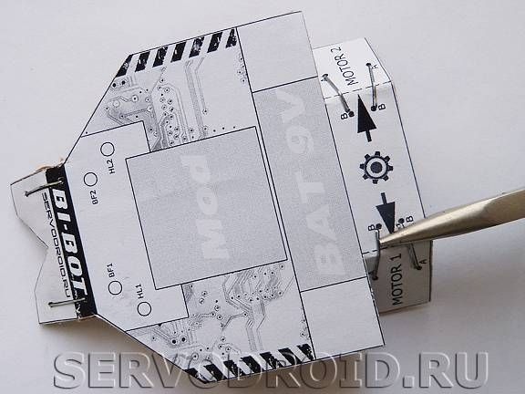
In the places designated as Mod "," BAT 9V "and" MOTOR 1 "," MOTOR 2 "stick the strips of double-sided tape.
Step Four Installation of motors
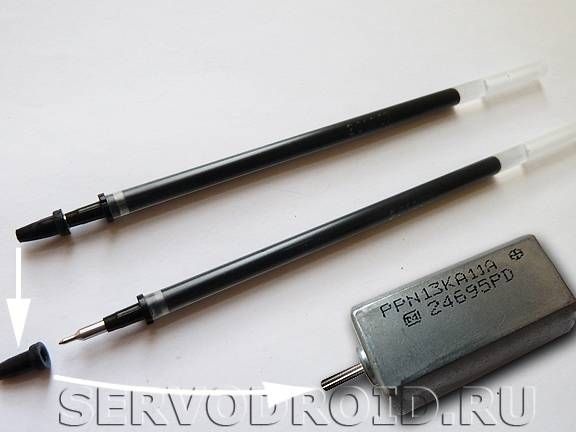
Motors are mounted in position with nylon ties. To prevent shafts from slipping, they must be worn with protectors. They are made of rubber bands, which are in the helium rods of pens. At the same stage, solder the wires to the motors.
Step Five Installation of infrared LEDs
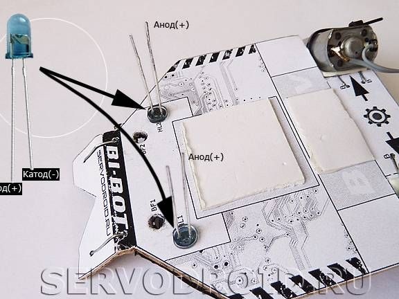
When installing infrared LEDs, it is important not to confuse their conclusions, for imported elements a long contact is an anode, that is, a plus. LEDs are installed at positions HL1, HL2 as shown in the photo. The findings are bent so that the diodes can be connected in parallel.
A 430 ohm resistor must be soldered to the positive contact of the LEDs, and a black wire to the negative contact.
The other end of the black wire must be connected to the center pin of the three-section terminal block. As for the output of the resistor, it is connected to the terminal of the terminal block.
Step Six Final build phase
In order for the robot to move along the line, phototransistors are put in place BF1, BF2 as in the photo.
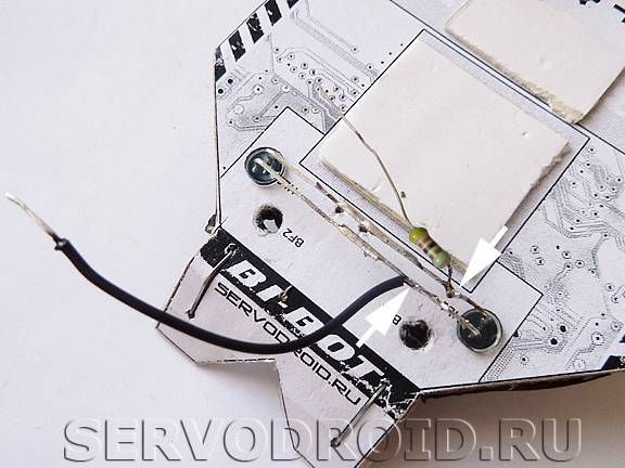
Transistors for movement behind the light source are placed on the back side.
In conclusion, the motors are connected, and the battery is put.
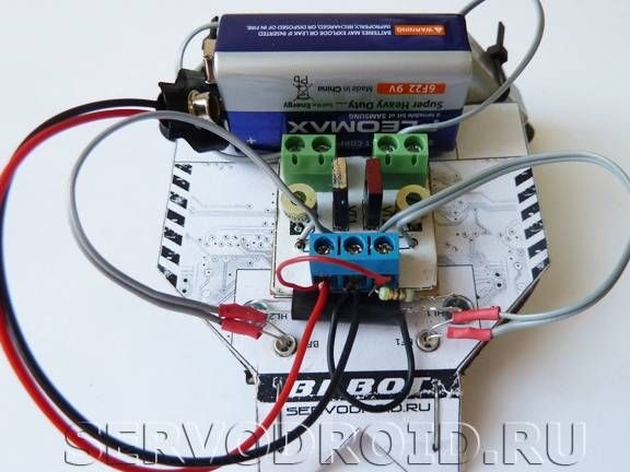
That's all, the robot is ready. Now you can try to turn it on and configure it to the desired conditions.