To make it you will need:
-Li-ion battery
Li-Ion battery charge controller
3-5V boost converter
well and of course wires, switch and molecular glue
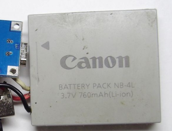
So, the first thing to do is pick up the battery. You can find it in an unnecessary / broken mobile phone, mp3 player, camera, etc. The voltage of this battery should be 3.7 volts, and the larger the capacity, the better. It is clear that the battery must be working, since it is he who often causes the failure of a long-used mobile phone. In this design, a 760mAh battery is used. In other words, an ordinary battery lying around idle.
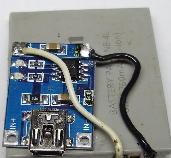
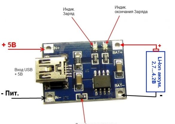
In order to verify its operability, you will need a Li-Ion battery charge controller. In this design, the cheapest version of the Tp4056 was used. It looks like this:
You can find it in any radio store, and its cost is $ 0.5. He will charge the battery from the USB current, which will be set by the selection of the resistor marked in the picture.
This unit comes from the manufacturer with a 1.2 kΩ resistor, which corresponds to the maximum charge current for this unit - 1 ampere. Here is a table by which you can select the value of the current-sensing resistor:
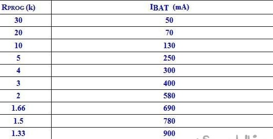
In this design, a current-sensing resistor with a nominal value of 2.2 kOhm is used, which corresponds to a maximum charge current of 500-550 mA. The maximum charge current is selected so that it does not exceed the battery capacity, since a significant excess of the charge current will necessarily lead to battery failure.
There are two LEDs on the block, one red, signaling the battery charging process, the second blue, signaling the end of charging. After filling the entire structure with transparent hot-melt adhesive, they beautifully illuminate the entire device.
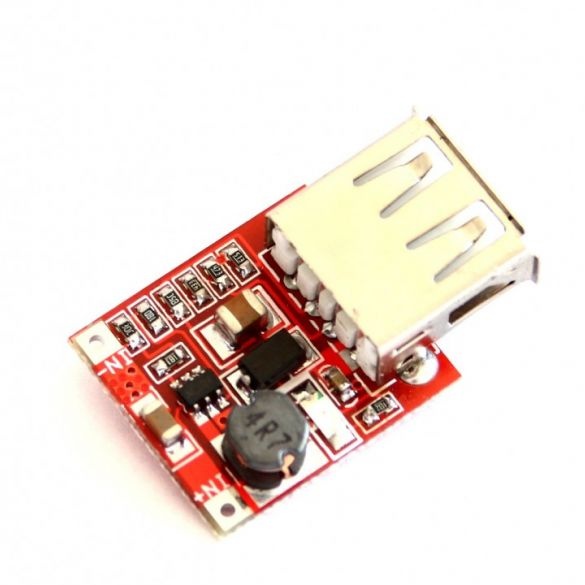
After the battery has been charged and tested under load, thereby showing its operability, a 3-5 volt boost converter is soldered. It can be industrial production, for example, like this:
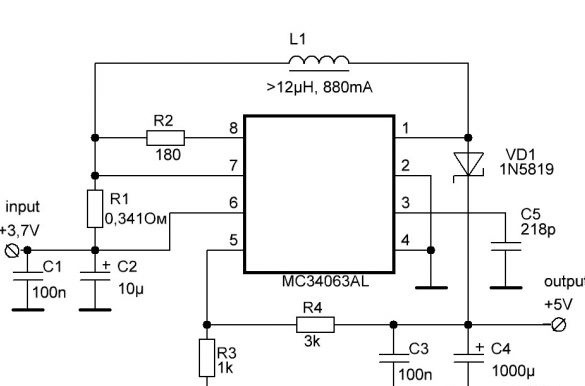
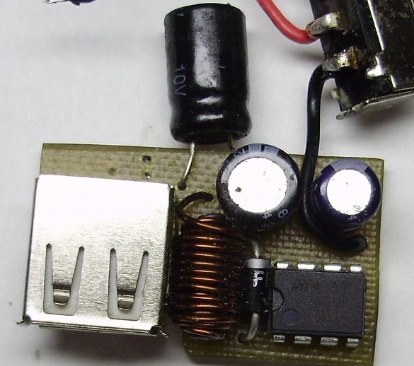
They call it “3-5V to 5V 1A Adjustable Step-up Power Supply Module with USB Output”, or it can be manufactured independently on the basis of the widely used mc34063 chip.And since there was already a homemade one, it was used. There is plenty of information on its calculation and manufacture on the Internet, so it makes no sense to dwell on the manufacture of the converter. Here is his diagram:
The conversion frequency is 100 kHz, set by the capacitance of the capacitor C5. Inductance is wound on a small ferrite core from some old radio receiver with a wire with a cross-section of 0.5 mm in diameter. This is a fairly thick wire, but it can significantly increase the efficiency of the device. R1 limits the input current of the converter (protects the battery from short-circuit), the divider R3, R4 sets the output voltage to exactly 5 volts, capacitors C3 and C4 smooth out the voltage fluctuations. The VD1 diode is a Schottky diode with a small voltage drop, its use also increases the efficiency of the converter.
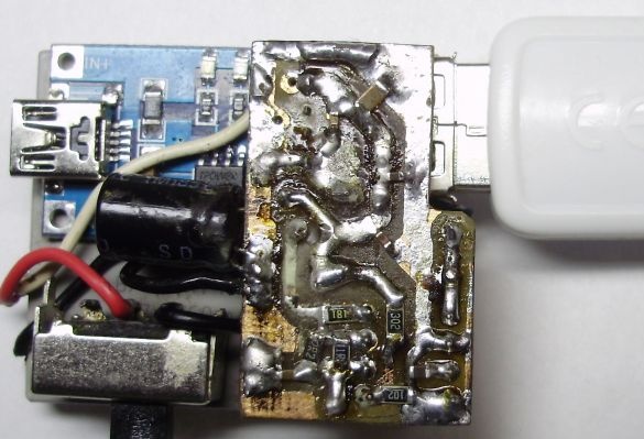
A switch is installed in front of the boost unit to prevent the battery from being discharged during downtime.
Here is a general diagram of the device:
Now the structure is soldered and ready for pouring with hot glue. It will not be superfluous to check everything again.
Finally, the entire structure is filled with hot-melt adhesive for mechanical strength and at least some kind of waterproofing.
Everything, the device is ready. Now it is once again connected to USB for charging (the red LED lights up):
After a while, the battery is charged and the blue LED lights up.
This means that now the device is ready to power and charge any USB-consumer.


