

A power supply is a necessary thing in the arsenal of any radio amateur. And I propose to assemble a very simple, but at the same time stable circuit of such a device. The scheme is not difficult, and the set of parts for assembly is minimal. And now from words to action.
The following components are needed for assembly:
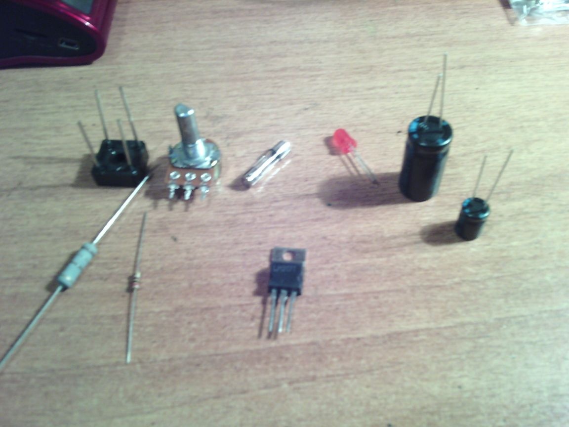
Immediately bring the diagram:
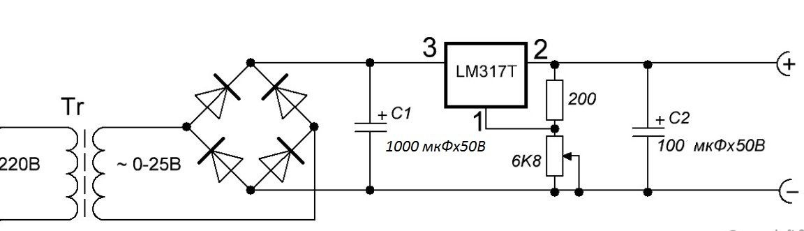
The LM317 chip is a voltage regulator. It is on it that I will assemble this device.
And so, we proceed to the assembly.
Step 1. First you need to determine the resistance of resistors R1 and R3. The thing is which transformer you choose. That is, you need to select the correct denominations, and a special online calculator will help us with this. It can be found here at this link:
I hope you can figure it out. I calculated the resistor R2, taking R1 = 180 Ohms, and the output voltage is 30 V. In total, it turned out 4140 Ohms. That is, I need a 5 kΩ resistor.
Step 2. We figured out the resistors, now it's up to the printed circuit board. I did it in the Sprint Layout program, you can download it here:
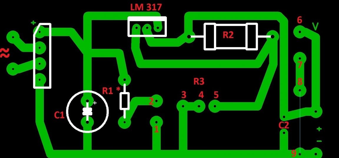
Step 3 First, I will explain what to solder. To pins 1 and 2 - LED. 1 is the cathode, 2 is the anode. And we consider the resistor for it (R1) here:
To contacts 3, 4, 5 - a variable resistor. And 6 and 7 were not useful. This was intended to connect a voltmeter. If you do not need this, then simply edit the downloaded board. Well, if necessary, then install a jumper between 8 and 9 pins. I made a pay on getinax, using the LUT method, etched in hydrogen peroxide (100 ml of peroxide + 30 g. Citric acid + teaspoon of salt).
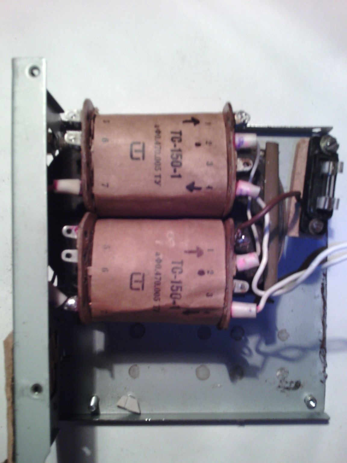
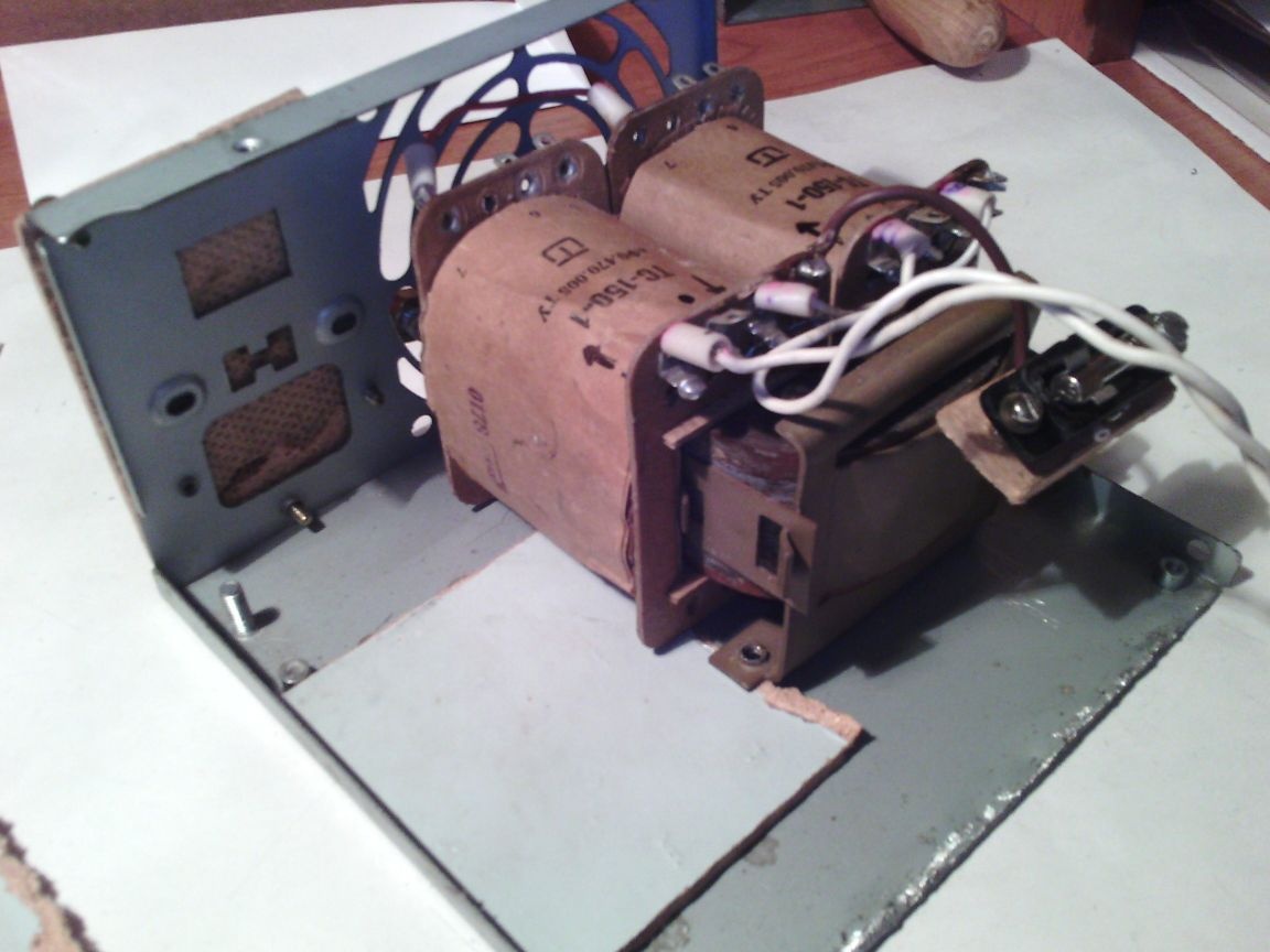
Now about the transformer. I took the power transformer TS-150-1. It provides a voltage of 25 volts.
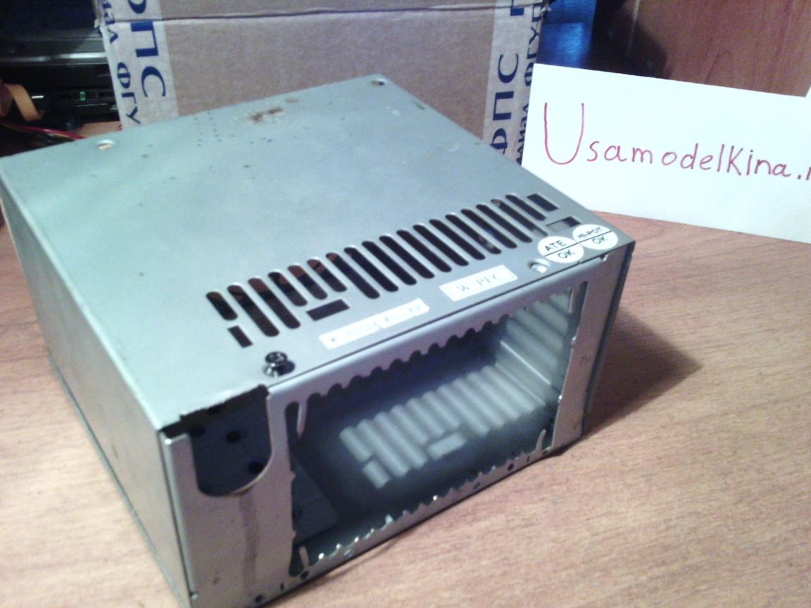
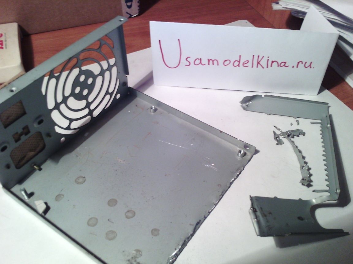
Step 4 Now you need to decide on the body. Without thinking twice, my choice fell on the case from the old computer power supply. By the way, in this case there used to be my old PSU.
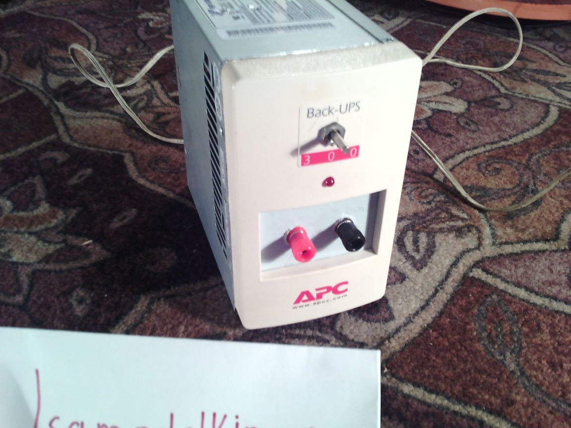
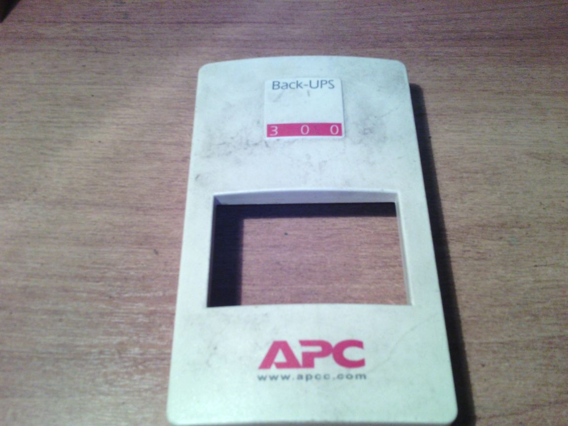
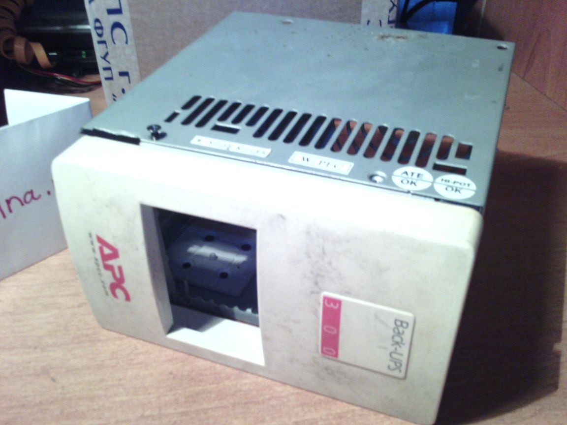
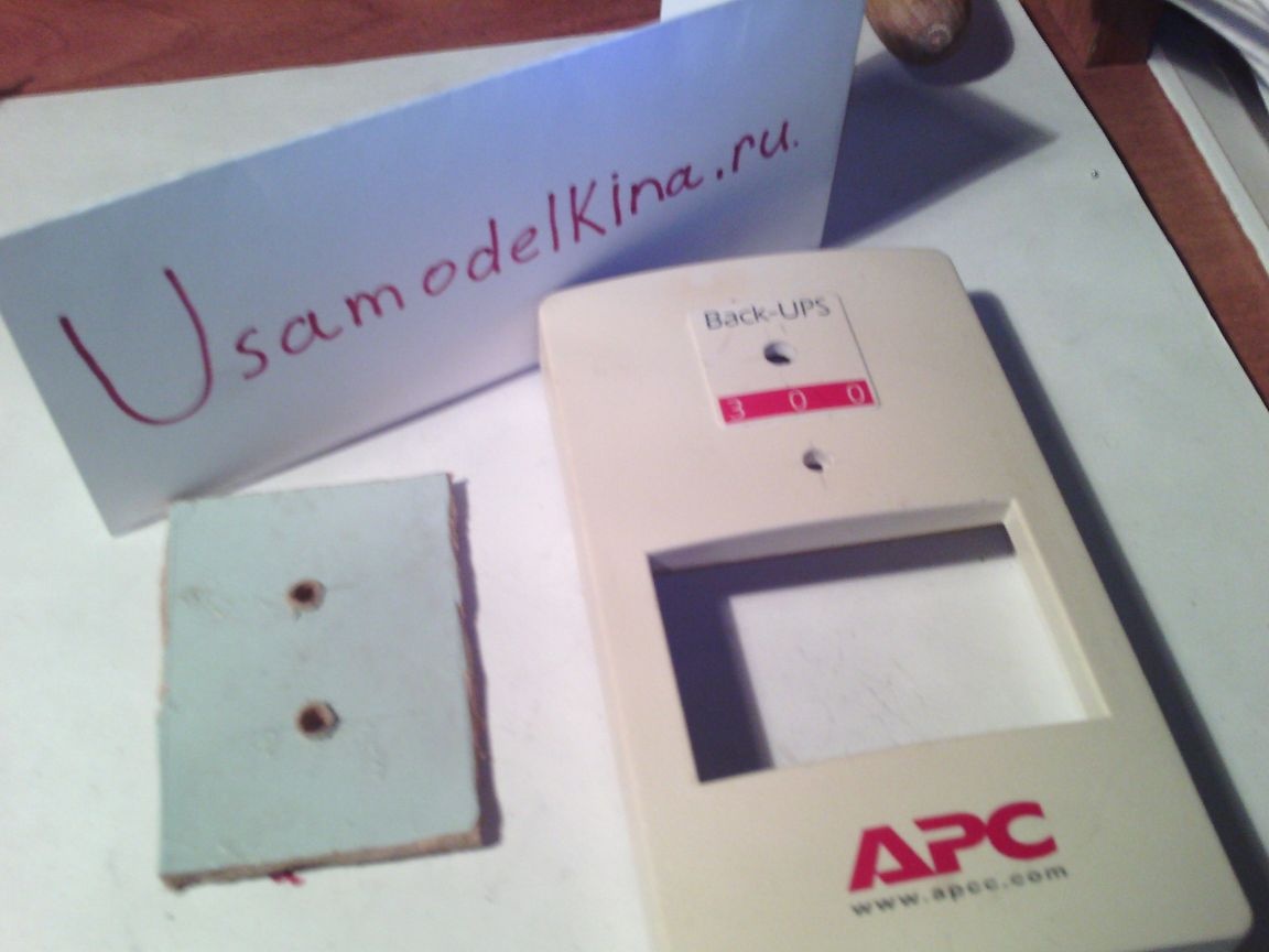
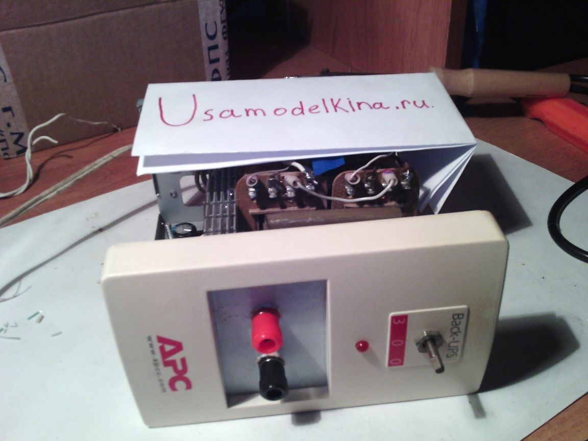
I took the front panel from the uninterruptible, which fit very well in size.
This is how it will be installed approximately:
Next, you need to break the front of the case to secure the panel. Then process the sharp edges with a file.
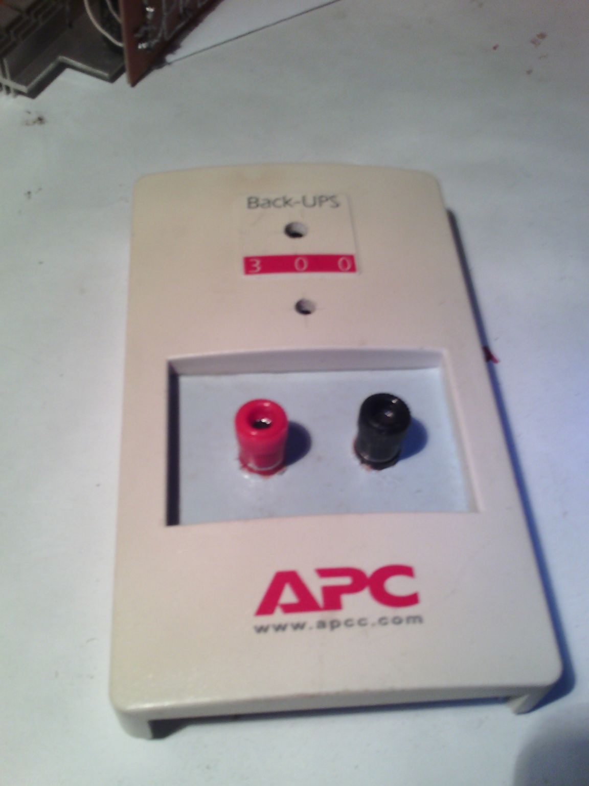
To close the hole in the center, I pasted a small piece of fiberboard, and drilled all the holes I needed. Well, I installed Banana connectors.
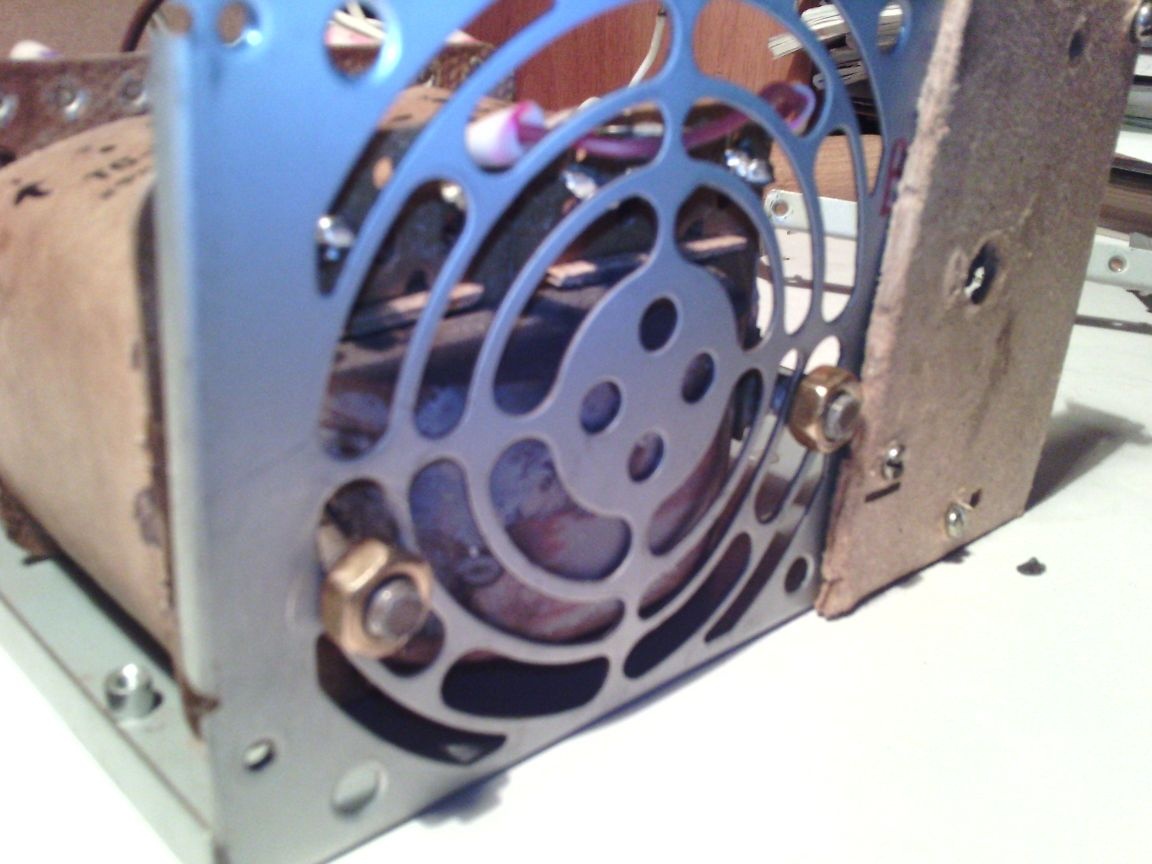
The power button is left behind.Her photo is not yet. I fixed the transformer with the "native" nuts to the rear fan grill. He just fit in size.
And in the place where there will be a board, I also pasted a piece of fiberboard in order to avoid a short circuit.
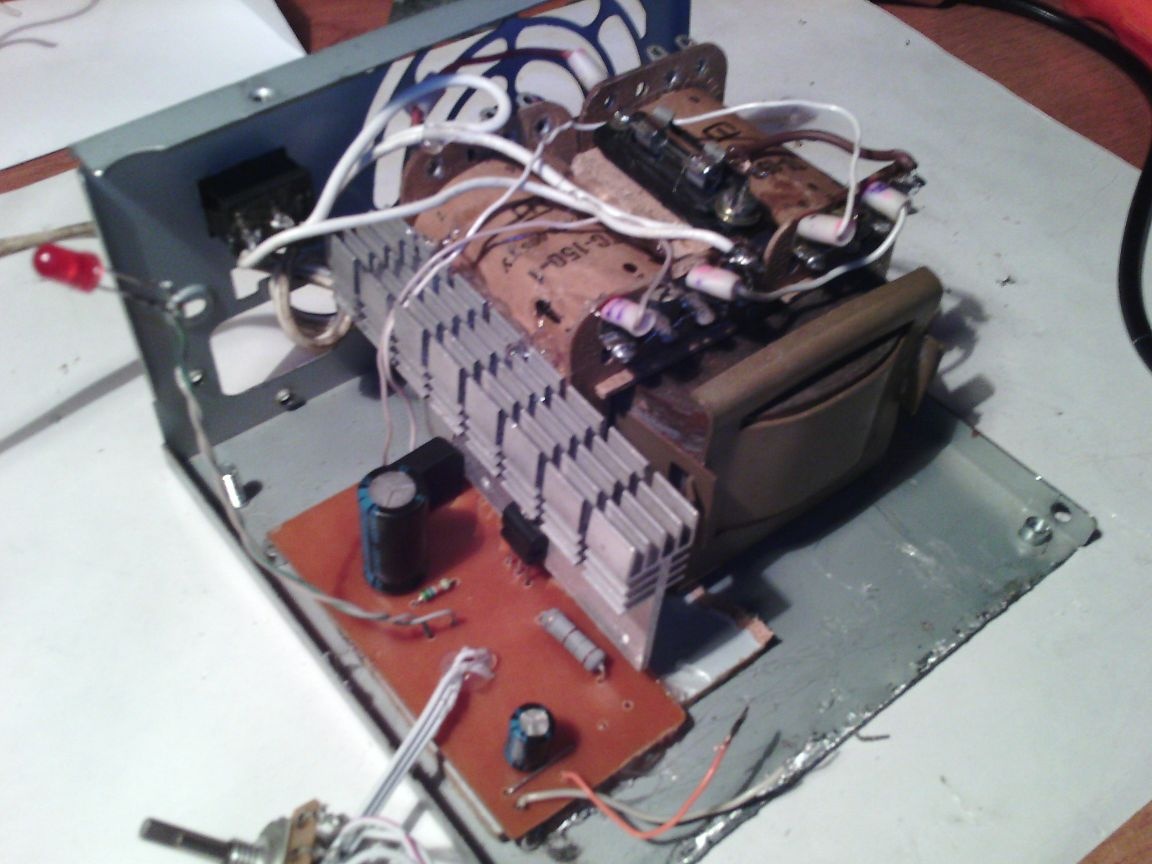
Step 5. Now you need to install the board and radiator, solder all the necessary wires. And do not forget about the fuse. I attached it on top of the transformer. In the photo it all looks somehow scary and not beautiful, but wearing it is not at all like that.
Step 6 Next, install the front panel. I glued it to hot melt. We insert an LED into the drilled holes, we fasten a variable resistor, I already installed the banana connectors earlier.
It remains only to close the top cover. I also glued it a little on hot-melt adhesive to the panel. And now our power supply is ready! It remains only to test it.
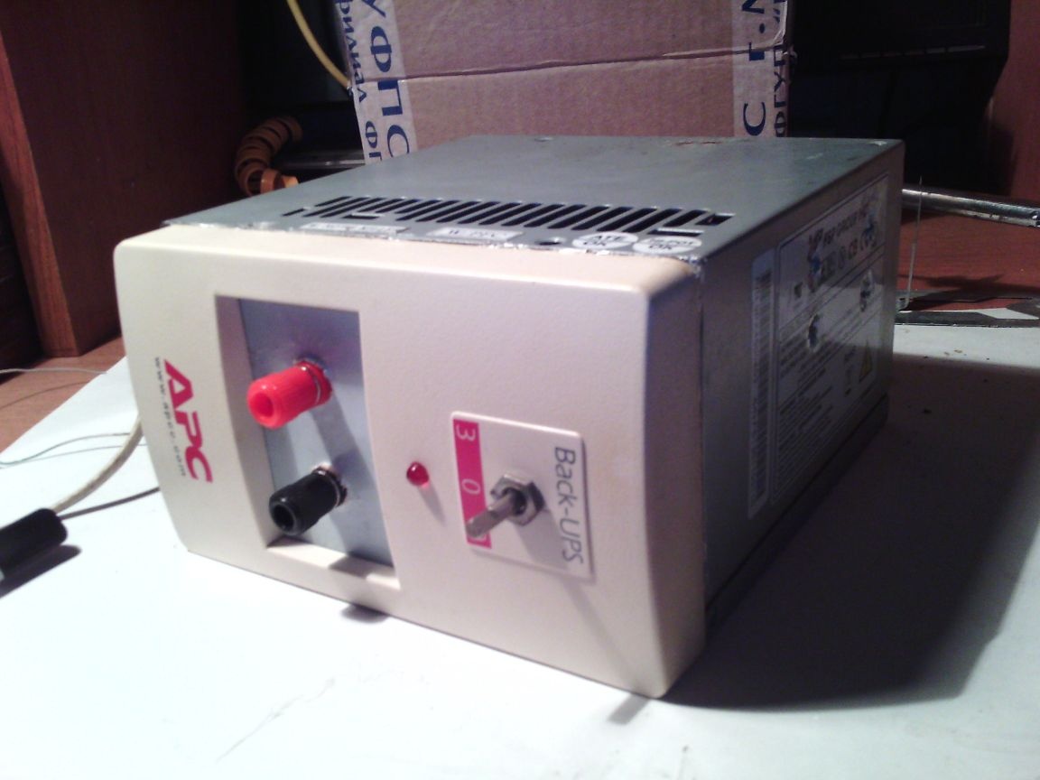
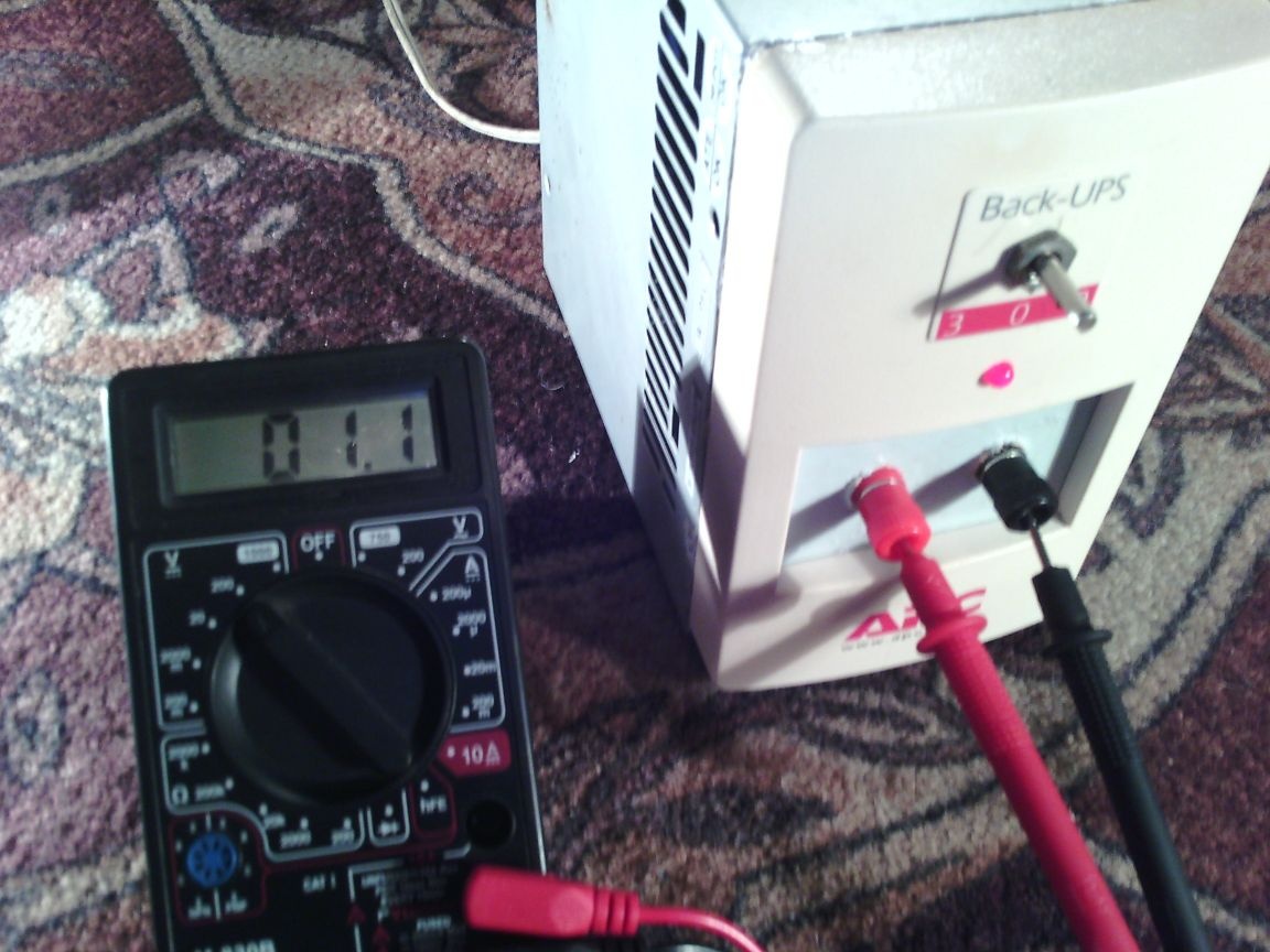
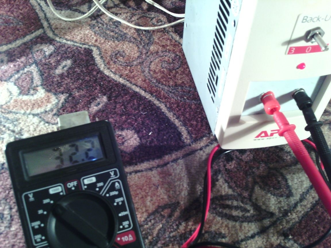
This unit is capable of delivering a maximum voltage of 32 V and a current strength of up to 2 amperes. The minimum voltage is 1.1 V and the maximum is 32 V.
Thank you, good luck to everyone!