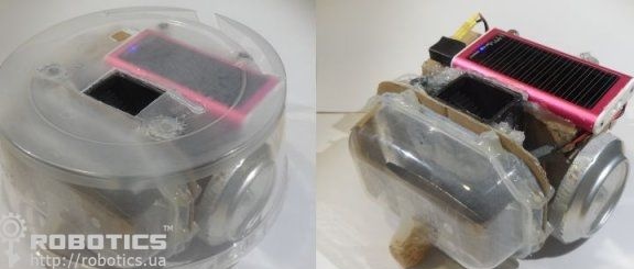
In the world, every day more and more popular among robotic cleaners. Thanks to such small helpers, the house becomes much cleaner, and much less effort is put into cleaning. There are a lot of different modifications of robots, they all differ in functionality, size and other parameters.
Specifically, this article will consider an example of how
do it yourself You can make a simple robot, which itself will vacuum the room when necessary. The controller is used here as the “brain”
Arduino.
Materials and tools for the manufacture of the robot: - board that controls the operation of engines (Arduino motor shield);
- Arduino board;
- two motors with gears (motors at 3 volts and a rotation speed of about 100 rpm.);
- wheels (can be made of aluminum cans;
- a cooler from a computer power supply (possible both on 5V and 12V);
- 5V power supply (battery);
- wires and plate for installation of radio elements;
- to make the case you will need a plastic container;
- Another small container for creating a waste bin;
- hot glue;
- magnets;
- cardboard.
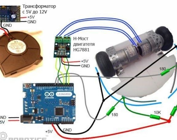
Step one. Software part of the robot and sketch:
The heart of the robot is the Arduino controller. To program it you will need a computer and special software.
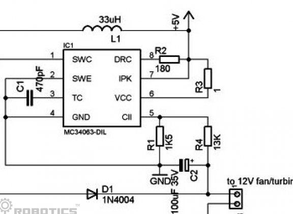
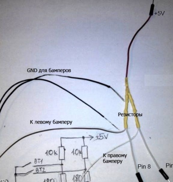
To download the sketch to the board, you will need the Arduino IDE program. Below you can take the program code of the robot and see the main circuit.
/*
Program for controlling a robot with two motors.
The robot turns when motors changes their speed and direction.
Front bumpers on left and right sides detect obstacles.
Ultrasonic sonars can be connected to analog inputs (tested on LV-MaxSonar-EZ1):
- put pins in array sonarPins in the following order: left, right, front, others ..
Examples:
1. only left and right sonars connected to pins 2 and 3: sonarPins [] = {2,3}
2. left, right and front sonars connected to pins 2, 3 and 5: sonarPins [] = {2,3,5}
3. only front sonar connected to pin 5: sonarPins [] = {-1, -1.5}
4. only left sonar connected to pin 2: sonarPins [] = {2}
5. only right sonar connected to pins 3: sonarPins [] = {-1,3}
6.5 sonars connected to pins 1,2,3,4,5: sonarPins [] = {1,2,3,4,5}
Motor shield is used to run motors.
*/
const int Baud = 9600; // UART port speed
// Sonar properties
int sonarPins [] = {1, 2}; // Analog Pin Nums to sonar sensor Pin AN
const long MinLeftDistance = 20; // Minimum allowed left distance
const long MinRightDistance = 20; // Minimum allowed right distance
const long MinFrontDistance = 15; // Minimum allowed front distance
const int SamplesAmount = 15; // more samples - smoother measurement and bigger lag
const int SonarDisplayFrequency = 10; // display only one of these lines - not all
int sonarDisplayFrequencyCount = 0;
const long Factor = 2.54 / 2;
long samples [sizeof (sonarPins)] [SamplesAmount];
int sampleIndex [sizeof (sonarPins)];
// right side
const int pinRightMotorDirection = 4; // this can be marked on motor shield as "DIR A"
const int pinRightMotorSpeed = 3; // this can be marked on motor shield as "PWM A"
const int pinRightBumper = 2; // where the right bumper is connected
// left side
const int pinLeftMotorDirection = 7; // this can be marked on motor shield as "DIR B"
const int pinLeftMotorSpeed = 6; // this can be marked on motor shield as "PWM B"
const int pinLeftBumper = 8; // where the right bumper is connected
// uncomment next 2 lines if Motor Shield has breaks
// const int pinRightMotorBreak = PUT_BREAK_PIN_HERE; // this can be marked on motor shield as "BREAKE A"
// const int pinLeftMotorBreak = PUT_BREAK_PIN_HERE; // this can be marked on motor shield as "BREAKE B"
// fields
const int turnRightTimeout = 100;
const int turnLeftTimeout = 150;
// set in counter how long a motor is running back: N / 10 (in milliseconds)
int countDownWhileMovingToRight;
int countDownWhileMovingToLeft;
// Initialization
void setup () {
Serial.begin (Baud);
initPins ();
// uncomment next 4 lines if Motor Shield has breaks
// pinMode (pinLeftMotorBreak, OUTPUT);
// pinMode (pinRightMotorBreak, OUTPUT);
// digitalWrite (pinLeftMotorBreak, LOW); // turn off breaks
// digitalWrite (pinRightMotorBreak, LOW); // turn off breaks
runRightMotorForward ();
runLeftMotorForward ();
startMotors ();
}
// Main loop
void loop () {
verifyAndSetRightSide ();
verifyAndSetLeftSide ();
processRightSide ();
processLeftSide ();
delay (10); // repeat every 10 milliseconds
}
//---------------------------------------------------
void initPins () {
pinMode (pinRightMotorDirection, OUTPUT);
pinMode (pinRightMotorSpeed, OUTPUT);
pinMode (pinRightBumper, INPUT);
pinMode (pinLeftMotorDirection, OUTPUT);
pinMode (pinLeftMotorSpeed, OUTPUT);
pinMode (pinLeftBumper, INPUT);
for (int i = 0; i pinMode (sonarPins [i], INPUT);
}
void startMotors () {
setMotorSpeed (pinRightMotorSpeed, 255);
setMotorSpeed (pinLeftMotorSpeed, 255);
}
void waitWhileAnyBumperIsPressed () {
while (checkBumperIsNotPressed (pinRightBumper)
&& checkBumperIsNotPressed (pinLeftBumper)) {
delay (20); // check every 20 milliseconds
}
}
void processRightSide () {
if (countDownWhileMovingToRight MinFrontDistance) // checks if the minimum allowed front distance is not reached
return
if (checkCounterIsNotSet (countDownWhileMovingToLeft)) // if the counter is not yet counting down
runLeftMotorBackward (); // run the right motor backward
countDownWhileMovingToLeft = turnLeftTimeout; // set the counter to maximum value to start it counting down
}
bool checkCounterIsNotSet (int counter) {
return counter = SamplesAmount)
sampleIndex [pinIndex] = 0;
samples [pinIndex] [sampleIndex [pinIndex]] = value;
return true;
}
long calculateAvarageDistance (int pinIndex) {
long average = 0;
for (int i = 0; i average + = samples [pinIndex] [i];
return average / SamplesAmount;
}
Step Two Preparation of the basic elements of the robot
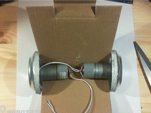
Cardboard is used as a base for fastening all components of the robot, including the battery, control boards and motors.
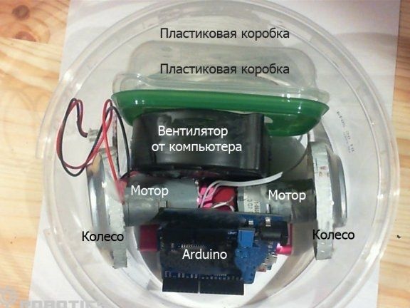
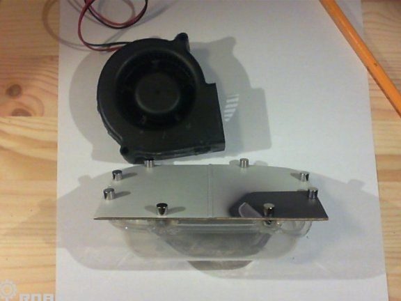
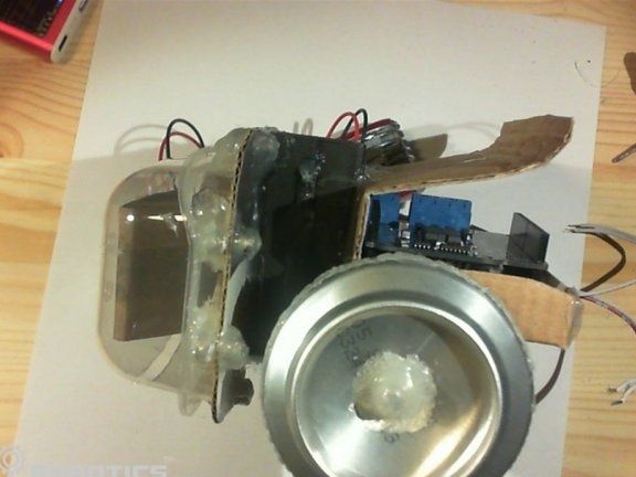
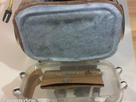
The turbine must be properly glued or otherwise fixed on a small plastic container in which to make a hole for the absorption of dirt. Subsequently, this design is glued to the cardboard base. In addition, the container must have an additional hole through which air will exit. There should be a filter, the author decided to use synthetic fabric for these purposes.
At the next stage, the cooler needs to be glued with servos, and then this design is installed on a cardboard base.
Step Three We make wheels for the robot
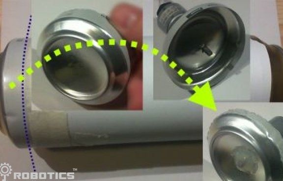
To make the wheels you need to take aluminum cans and cut off the upper and lower parts from them. Then these elements are glued together. Now it remains only to properly attach the wheels to the servomotors with hot melt adhesive. It is important to understand that the wheels must be fixed clearly in the center of the servo shafts. Otherwise robot will drive crookedly, and will use up energy.
Step Four The final robot assembly process
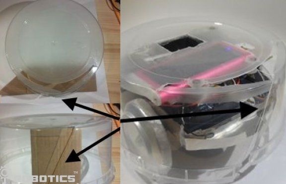
After the battery is installed and all the elements of the robot are connected, it remains to place the structure in a durable case. A large plastic container is great for these purposes. First of all, holes must be made in the nose of the robot body, through which contacts will be output that will give a signal electronics when the robot collides with an obstacle.
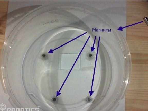
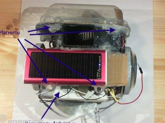
In order for the case to be quickly and easily removed, magnets are used to fix it, in this case there are eight of them. Magnets are glued to the inside of the vacuum cleaner and to the container itself, 4 pieces each.
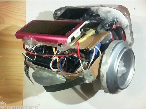
That's all. Now the robot is assembled, and it can be tried in practice. Despite the fact that the robot is not able to recharge on its own and has a rather limited ability in terms of navigation, in half an hour it will be able to clean up garbage in the kitchen or small room. The advantages of the robot is that all components can be easily found and they are not very expensive. No doubt homemade You can refine by adding new sensors and other elements.
