
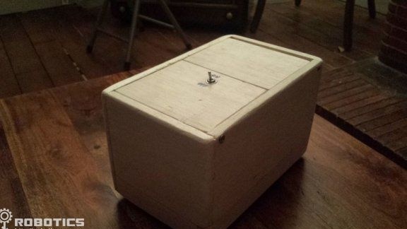
Robot DIY will be a great toy for children, also with it you can play relatives or friends. The essence of the robot is as follows. It is a box with a switch. As soon as someone clicks a switch on a box, a door begins to open, from which a hand comes out and puts the switch back to its original state. Despite the external simplicity of the robot, in fact, all this looks pretty funny.
The basis for creating a robot is a circuit Arduino. There are also some mechanical elements that will be discussed below. Let's consider in more detail how can do it yourself assemble such a robot.
Materials and tools for manufacturing:
- Arduino board, any with PWM outputs will do;
- servomotors, two pieces (suitable model Futaba - S3003, the power of such an engine is enough to open the door, the device produces up to 3.2 kg / cm of power);
- batteries;
- switch type SPST or SPTT;
- a switch to control battery power;
- you need a button to restart Arduino;
- wires, jumpers and other little things.
In addition, you will additionally need a gearbox (suitable for radio-controlled cars), a board for an electric motor called Arduino motor shield, an RC servo motor. These components are needed in order to make the box moving, like the author.
To reduce the noise level during operation of the device, an electrolytic type capacitor with a nominal value of 10mF, a 10K resistor, and an 74HC04 inverter are needed.
The manufacturing process of the robot:
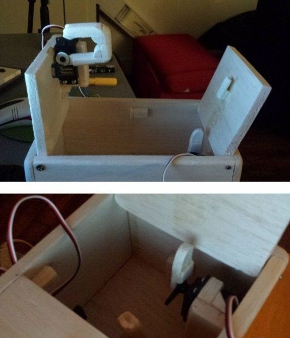
Step one. How to make a box
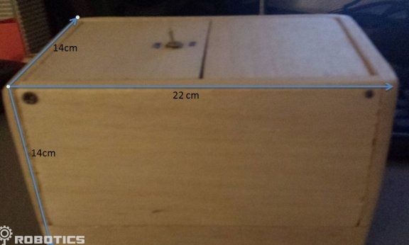
To create a box, that is, a robot body, you need to find plywood or cork. In addition, you need a powerful glue for gluing wood. It is important to understand that the more the structure weighs, the more energy will be consumed. As for the size of the box, it is 22cm x 14cm x 14cm.
Step Two Schematic diagram e parts
The top of the robot includes an Arduino main board, two servos, and a switch. As for the circuit, which is responsible for the amount of noise, it can be replaced with an ordinary resistor.
Servo drives are powered through the fifth pin of the Arduino board. As for the signal wires, they are connected to contacts 9 and 10. Thanks to these PWM contacts, the rotation angle of the servomotors is controlled. This is an angle from 0 to 180 degrees.
The red button is needed in order to restart the Arduino.
At the bottom of the circuit is the Arduino motor shield board.On the board you can see two channels, A and B, thanks to them, if desired, you can connect two motors at once. The main task of this board is that with it you can programmatically set the rotation speed, direction, breaks for any channel of the engines. If you look at the diagram, then channel B is used, while contact 13 determines the direction, contact 11 is speed, and contact 8 is used to control the brakes.
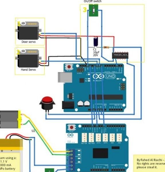
The power source is a 11.1 / 1000 mA battery, it connects to the Arduino motor shield board. If it will not be used, then the battery is directly connected to the main board.
Step Three Engine installation
The servo drive and hands are installed experimentally, you need to check in practice whether the mechanics are working correctly. To check the radius of deviation of the engines, you can use the Arduino IDE program.
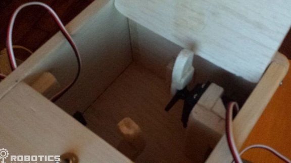
For the manufacture of hands taken wood of any kind. The main thing is that it is light, as otherwise the energy consumption will increase. As for the size of the hand, it is adjusted during installation, choosing the desired length, the desired effect is achieved.
The cover pusher and hand are mounted so that they do not touch the servomotor during operation.
Step Four We connect the servomotor and switch to Arduino
Using wires and jumpers, you need to connect all electronic elements to each other according to the specified scheme. The wires must be laid so that they do not interfere with the moving elements of the robot.
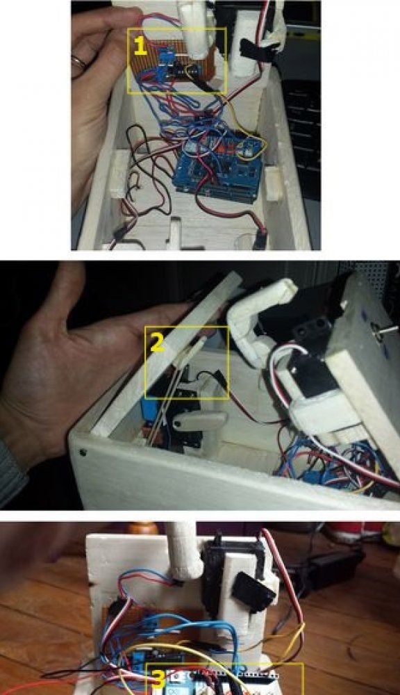
Under the number 1, you can see how it is connected and where the switching circuit is located. Number 2 marks such an element as an elastic band, it is needed in order for the door to open with some tension. Well, the number 3 indicates the engine shield installed on the Arduino.
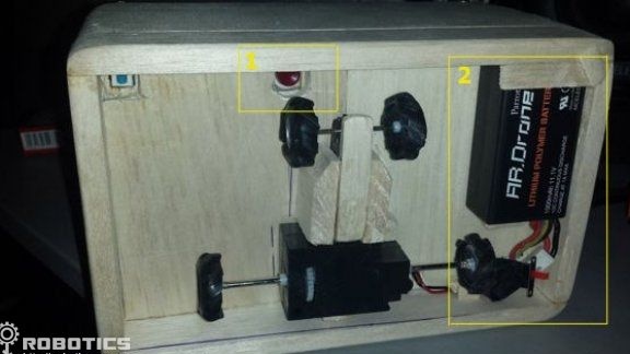
Step Five Installation of the mechanical part for moving the box
At the bottom of the box is a battery, an engine with wheels, a gearbox, a reset button, and a toggle switch to control the robot's power. Before attaching the elements, you need to calculate the balance of the weight of the box. In order for the robot to be stable, in addition to the leading axis, another additional one is installed.
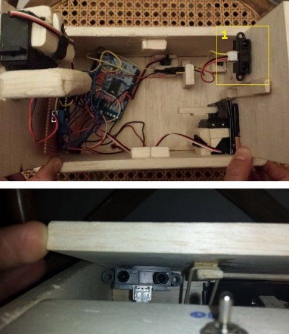
Step Six Another additional feature
In order for the robot to determine the direction of movement, it can be equipped with an IR sensor. At the same time, when someone tries to touch the toggle switch, the box will move right and left. For these purposes, the GP2Y0A21 sensor is suitable, it has three wires. Yellow must be connected to the third pin of Arduino, red to pin 5, and black to ground.
That's all, a simple and at the same time funny robot is ready. Such a toy will bring joy not only to the child, but also surprise many adults.
Firmware: