
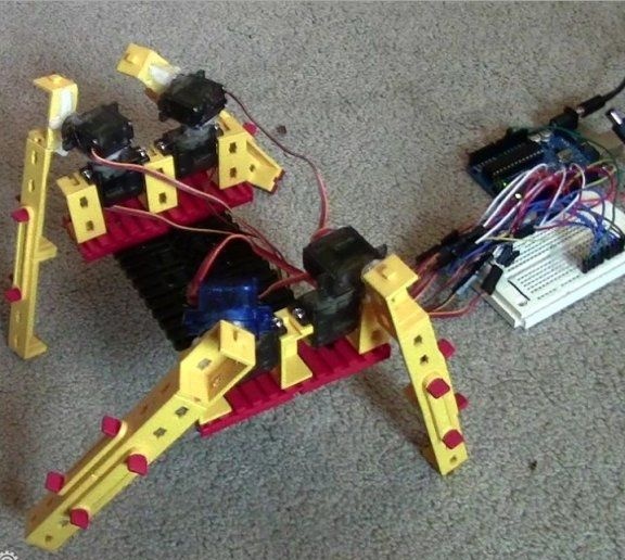
For those who decide to test their skills in the field of robotics and at the same time wish to explore the capabilities of the Ardunio platform, there is a great way to do this by assembling the spider robot, which will be described in this article. As the main strength elements due to which robot will move around are servos. As for the brain, here it acts as Arduinoas well as Fischertechnik. According to the author, the robot turned out to be quite interesting and promising.
Materials and tools for manufacturing:
- set of blades;
- hot glue;
- Dremel (need very thin drills);
- screwdriver;
- drill with a drill 7/32;
- Phillips screwdriver;
- blade;
- compartment for batteries;
- bread board.
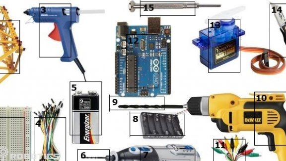
From electronics you will need:
- eight microservices with brackets;
- 6 AA batteries and clothespin;
- a lot of jumpers and connectors.
As the software part, you will need an Arduino with a power supply.
And parts need a Fischertechnik kit.
The manufacturing process of the robot. :
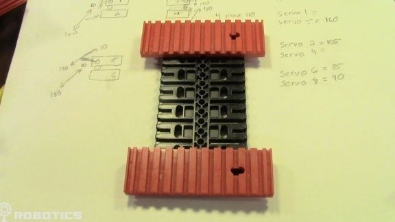
Step one. Create a robot frame
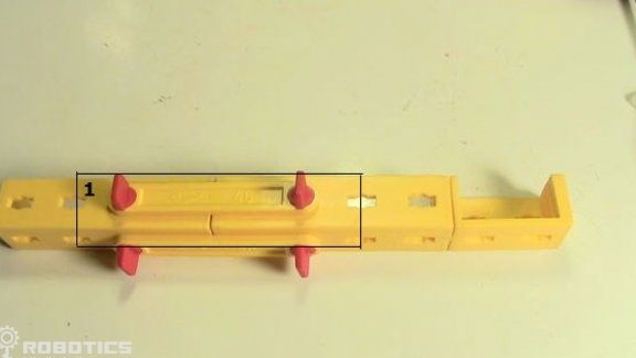
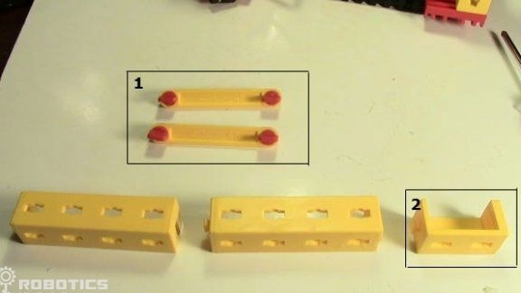
To make the frame, you need a Fischertechnik kit. How it should look can be seen in the photo. To create a frame, three tall "bricks" are needed, there must be four holes between them. Specifically in this homemade an element with 11 cuts will be used. It is important to make sure that all servos are operational.
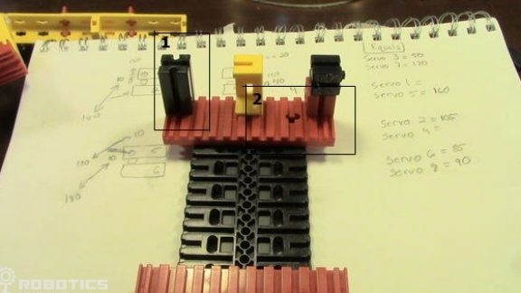
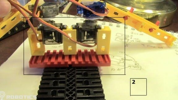
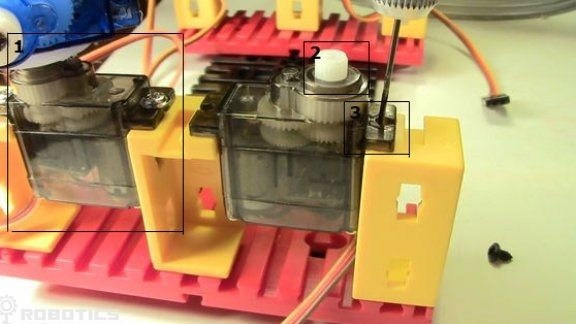
Step Two Install the servos
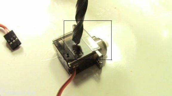
Servos will be installed between the "bricks". Servos are fixed with screws, for this purpose, holes must first be drilled in the attachment points using a dremel. Drill holes of the smallest diameter. However, hot glue is also suitable for these purposes, but in this case the design will be inseparable.
The second servo is installed on the other side reversed.
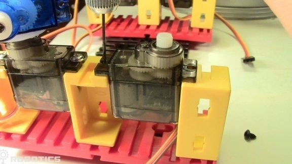
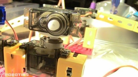
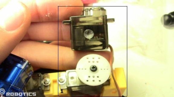
Step Three Installing one servo motor on another
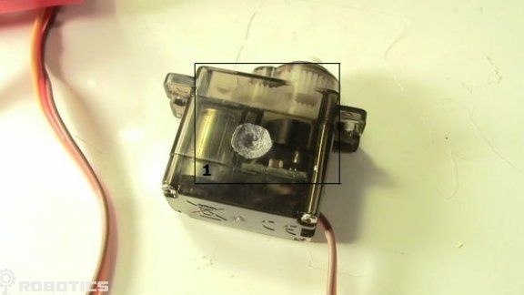
First of all, you need to deal with the mounting elements of the servos. If the engine rotates in the opposite direction, it must be turned all the way to the right.How to do this can be seen in the photo.
Specifically, in this case, the servo screw should protrude above the plastic, so it will be movable. In the housing of the second servo, you need to make a recess under the screw head.
what
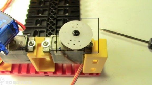
To connect the two servos, hot glue is used.
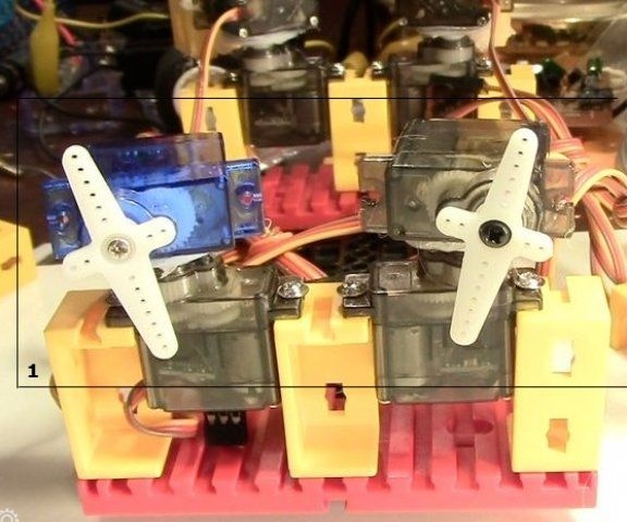
Step Four Connect legs
How to make legs, can be seen in the photo. There should be four of them.
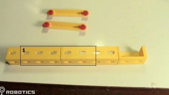
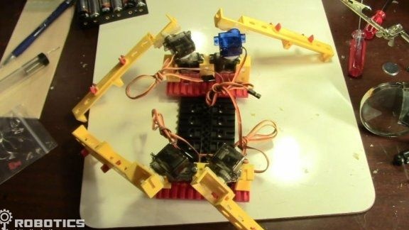
After the legs are assembled and connected to the robot, the design should look like in the photo.
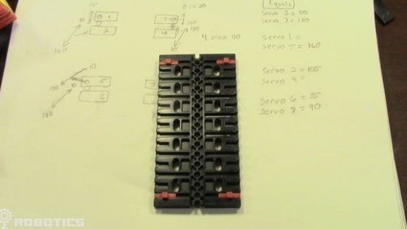
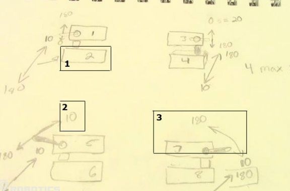
Step Five Creating a chart for a relationship
The diagram is needed in order to understand what angle each of the servos is capable of turning. Next, each servo drive is assigned a specific number, and on the basis of this number firmware will be created for the robot.
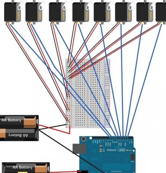
Step Six Bread board
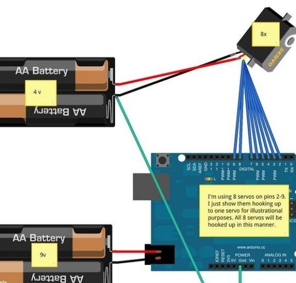
You need to pull out all 30 jumpers. Next, everything needs to be connected with wires as indicated in the diagram. Each servo drive has three contacts, one is responsible for grounding, power is supplied through one, and another is needed to control the motor.
The Vcc and GND servo pins must be connected to the Vcc and GND layout pins. Also, a 7.5V power supply is connected to the GND and Vcc layout channels.
The wires for controlling the servo are painted in orange and yellow. They connect to pins 2 and 9. For example, a contact from the first motor connects to the second pin on the Arduino. The second motor is already connected to the third contact and so on.
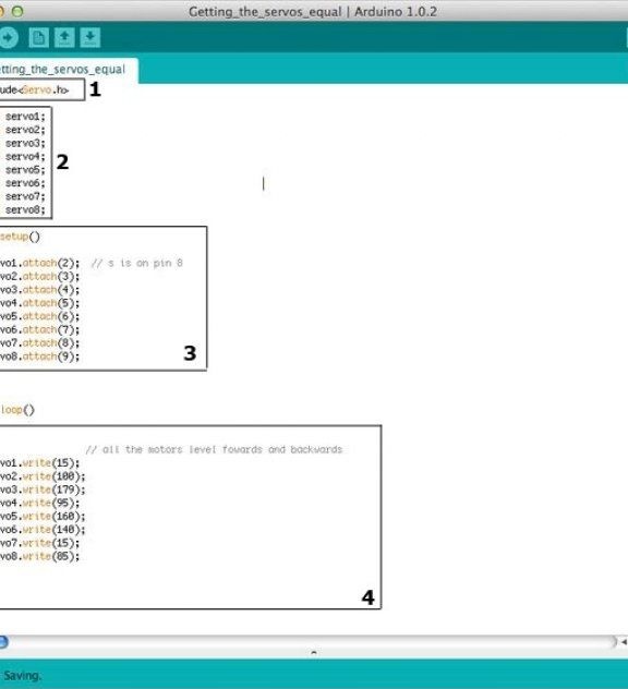
Seventh step. Set up servos.
Now it is time to create program code for the robot. First of all, on Arduino you need to create a new project to synchronize the engines. How the code should look can be seen in the photo. Thanks to this code, the legs of the robot are aligned.
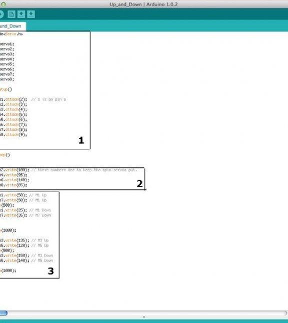
In order for the spider to rise, you need to create another project called Up and Down. Thanks to this code, the legs of the spider will be able to move up and down.
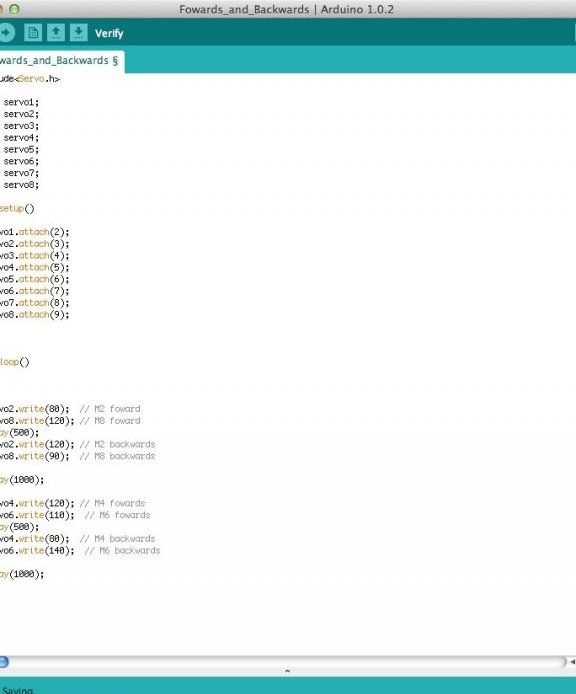
So that the robot can move forward and backward, you also need to create another project. How it will look can be seen in the photo.
And finally, for the robot to go, you need to combine the front and back. As can be noted, the program code of the robot consists of four blocks.
That's all, the robot is ready. Now it is possible to install various sensors on it, which will allow the robot to navigate in space. You can also make the robot hands so that it can take objects. In general, it all depends on the enthusiasm and imagination of the robot builder. However, even in this form, the robot behaves quite interestingly.
Firmware: