
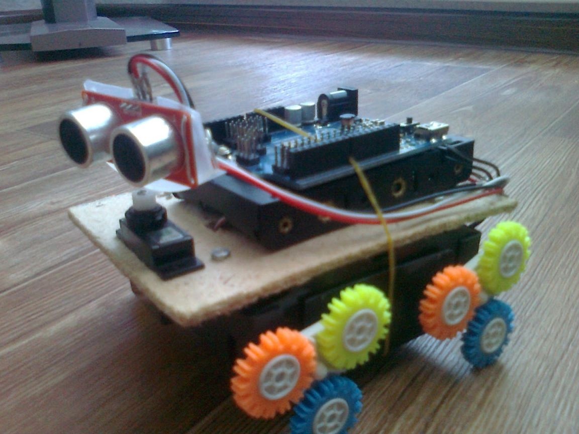
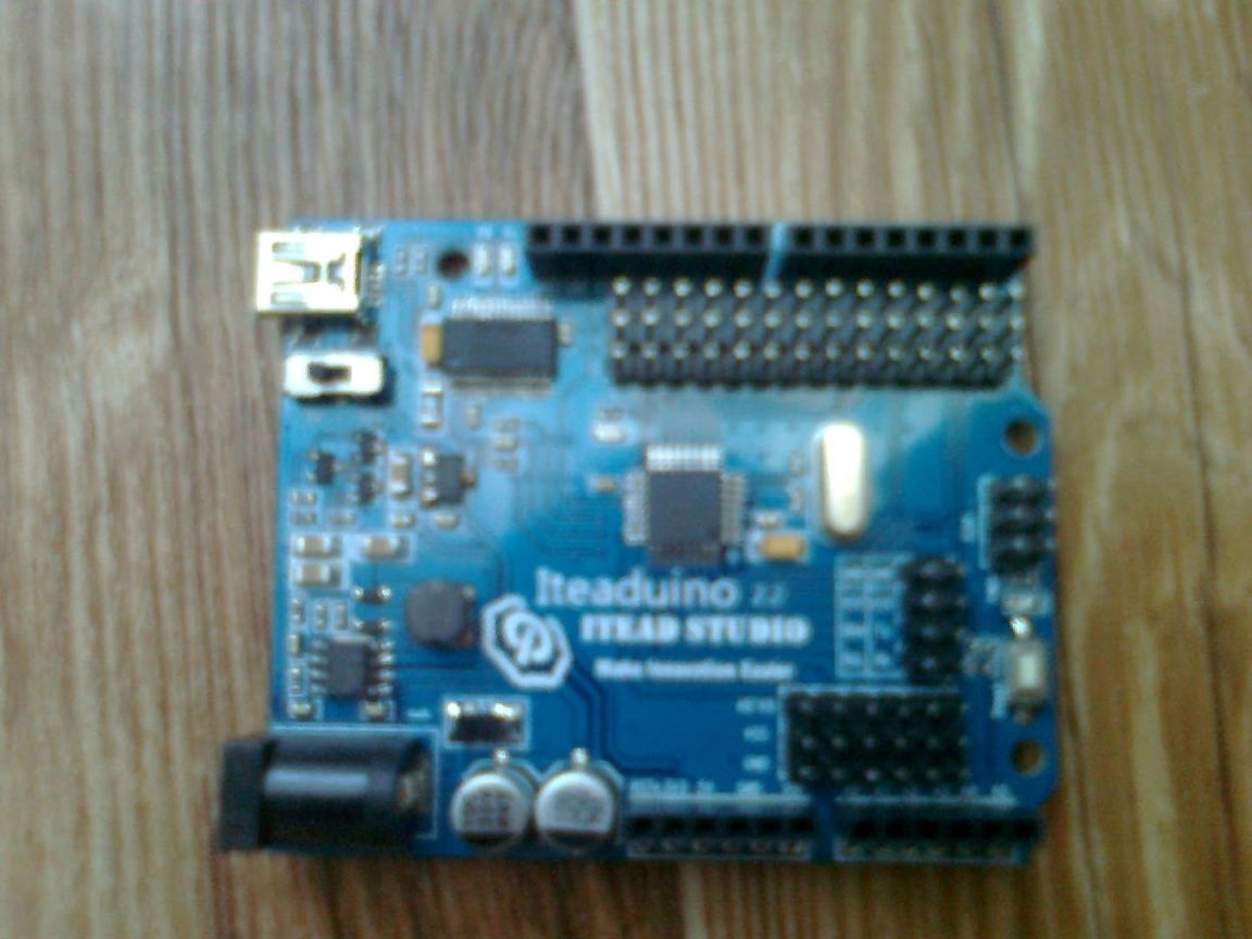
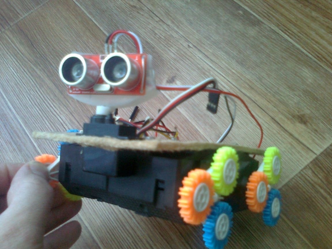
One author decided to share his "brainchild" based on the controller Arduino. The result is pretty funny robot, who can see obstacles in front of him, analyze the situation and then, only having chosen the best route, moves on. The robot was very maneuverable. It can rotate 180 degrees, and the rotation angle is 45 and 90 degrees. As the main controller, the author used Iteaduino, which is an analogue of Arduino.
Materials and tools for the manufacture of the robot:
- microcontroller (Arduino or similar Iteaduino);
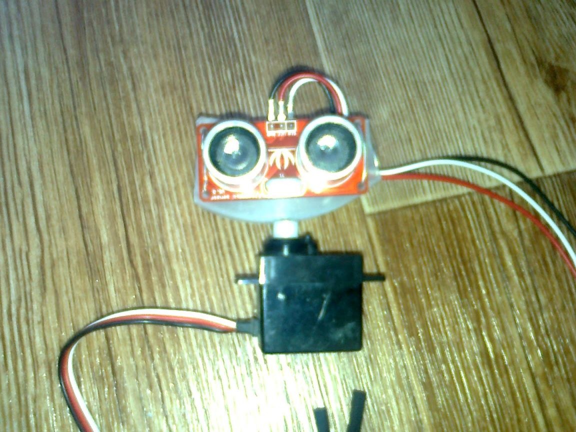
- ultrasonic sensor;
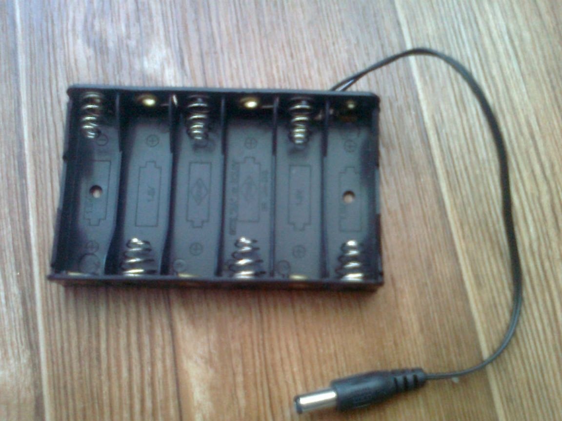
- holder for batteries;
- Chinese toys to create a wheelbase (you can buy ready-made);
- nippers;
- glue;
- wires;
- motors;
- fiberboard;
- jigsaw;
- transistors (D882 P).
The manufacturing process of the robot:
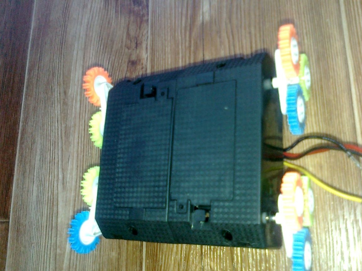
Step one. Creating a wheelbase
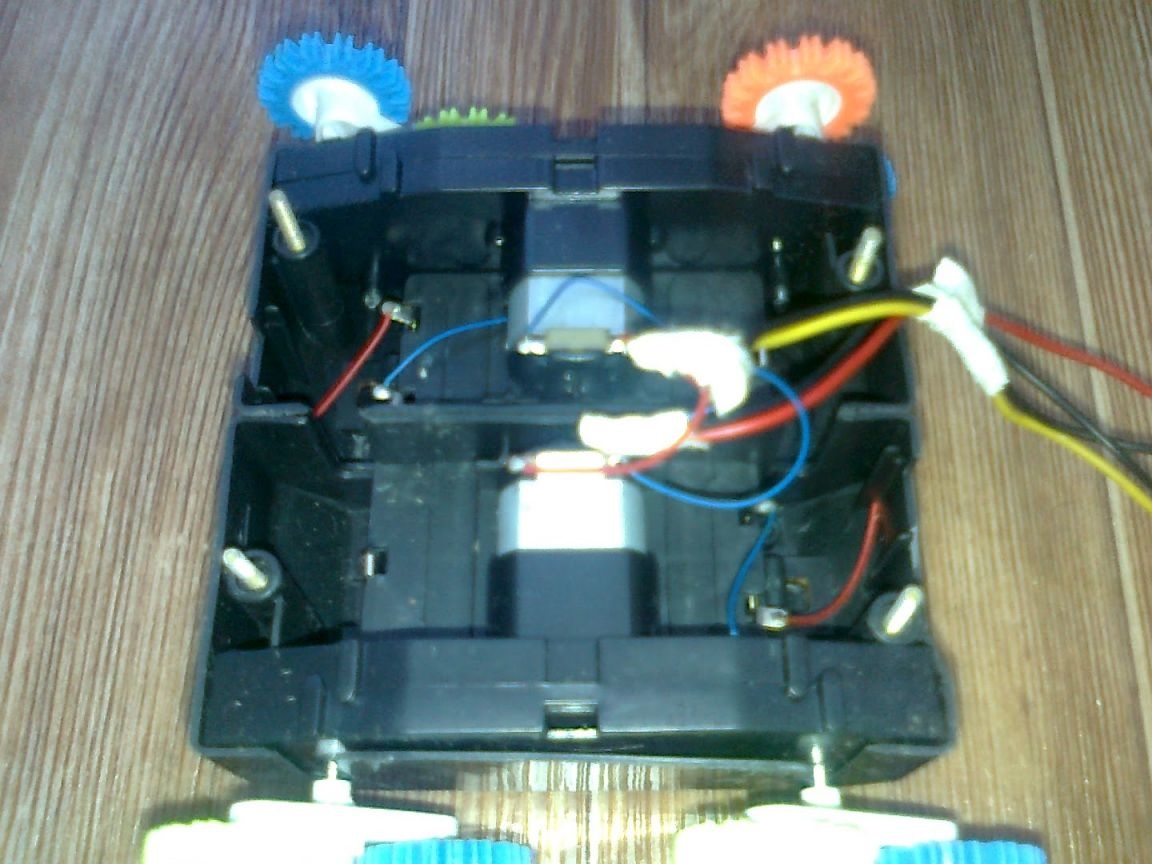
In order to create a wheelbase, the author bought two Chinese toy cars. However, there is no need to worry about this if you have extra money, since you can buy a ready-made base. With the help of nippers, the machines were cut into two parts to form two leading axes. Further, these parts were glued together. However, in this case, you can work with a soldering iron, the plastic is perfectly soldered.
When choosing cars, it’s best to take toys with ordinary wheels, since, according to the author, the robot jumps a lot with spikes like his.
There is another such moment when wires will be output from the motors, on one of them you must remember to change the polarity.
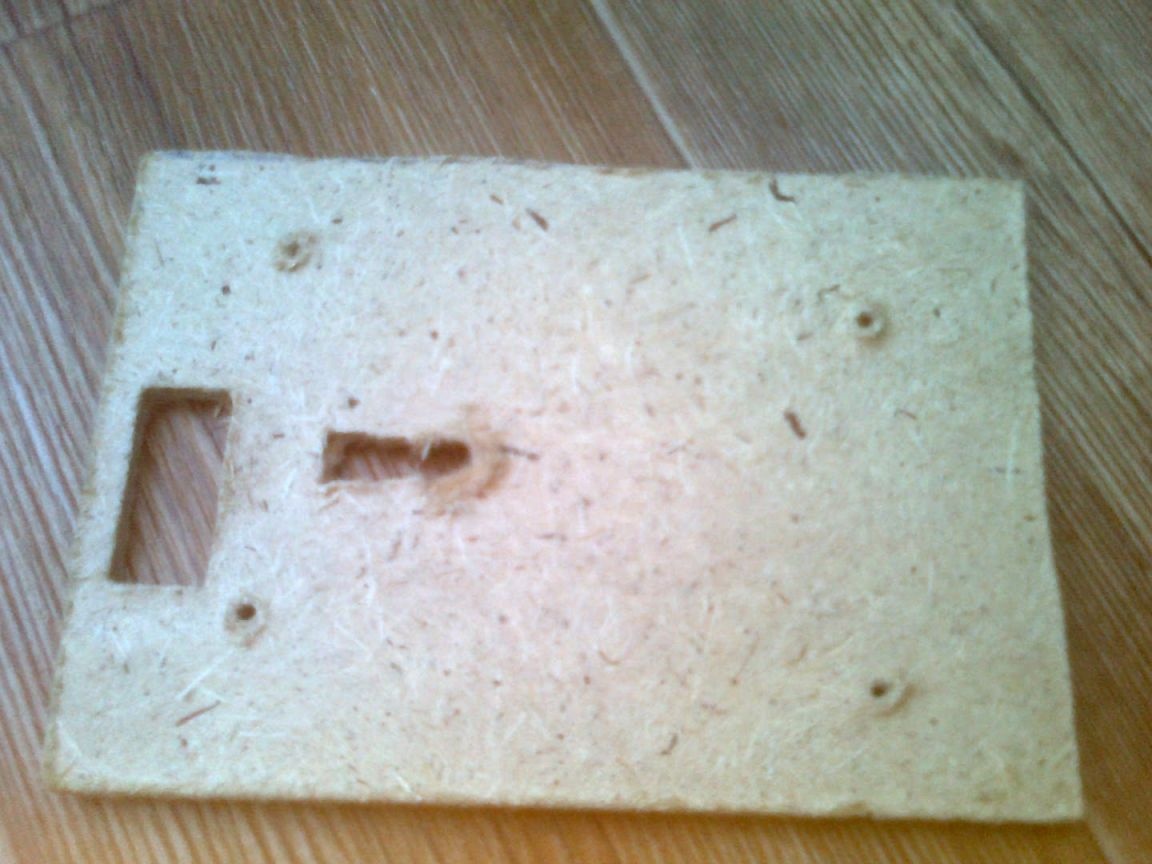
Step Two Making the top cover
The top cover of the robot is made of fiberboard, you can also use thick cardboard for these purposes. In the cover you can see a rectangular hole, it should be located so that the axis of the servo drive, which will be inserted into it, is located symmetrically. As for the hole in the middle, wires will be output through it.
Step Three Stuffing robot
To connect the chassis, it is best to use a separate power source, since it requires 9V to power the controller, and only 3V for motors. In general, battery holders are already integrated in the chassis of such machines, they just need to be connected in parallel.
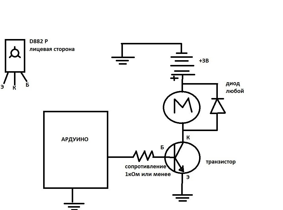
The motors are connected to the controller using transistors such as D882 P. They were pulled out of the old control panel of the machine. It is best of course to use power transistors such as TIP120B, but the author chose simply according to the appropriate characteristics. All electronic part is connected according to the specified scheme.
After flashing the robot, it will be ready for testing.In order for the robot to have time to turn around at a certain angle, you need to choose the right time for the motors.
As for the sensors, the ultrasonic must be connected to the 7th digital output of the microcontroller. The servomotor is connected to the 3rd digital input, the base of the transistor of the left motor is connected to 11th contact, and the base of the right to the 10th.
If Krona is used as power, then the minus is connected to GND, and the plus to VIN. Also to GND you need to connect the emitter of the transistor and the negative contact from the power supply of the chassis of the robot.
Firmware: