
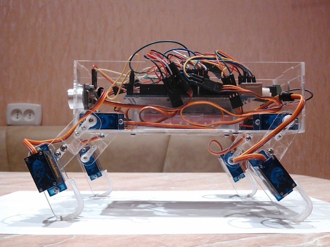
One author decided to share his first robot called Z-RoboDog. The peculiarity of the robot is that it looks like a dog, and behaves in a similar way. He knows how to walk forward and stops when an obstacle arises in front of him. First of all robot was done with the expectation of profitability, that is, a minimum of materials and means was spent. Let's consider in more detail how do it yourself You can create such a robot.
Materials and tools for the manufacture of the robot:
- 1 Arduino Mega or Uno (Mega is used in this version);
- pieces of plexiglass (the body and legs will be made from it);
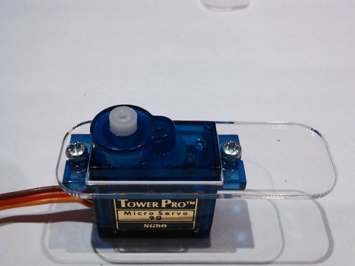
- a servo drive (the author used TowerPro SG90, only 8 pieces are needed);
- 1 ultrasonic rangefinder type HC-SR04;
- battery type 18560, 3.7V (the author used TrustFire 2400 mAh 2 pieces);
- holder for batteries of sample 18560 (the author used redone packaging);
- a rack for the printed circuit board 25 mm (4 pieces);
- breadboard element;
- jumpers-wires;
- 18 screws DIN 7985 M2, 8 mm;
- 18 nuts DIN 934 M2;
- drill or screwdriver.
Robot assembly process:
Step one. Production of the robot body
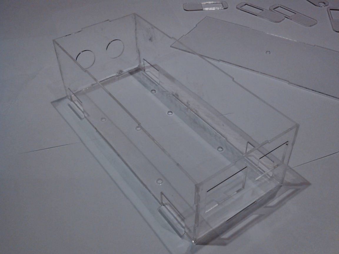
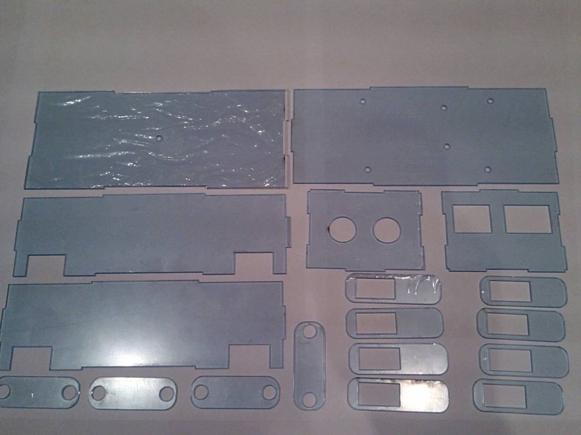
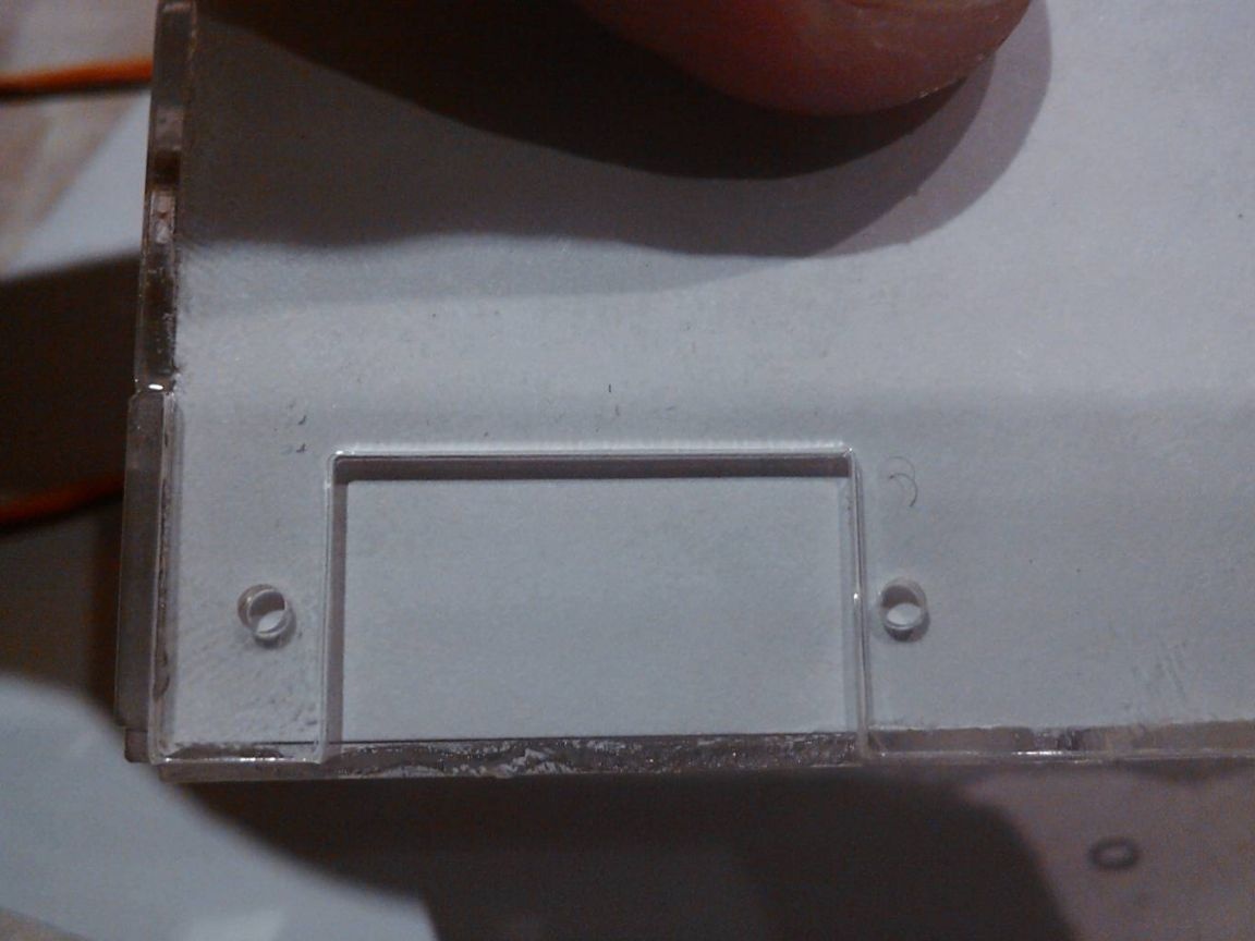
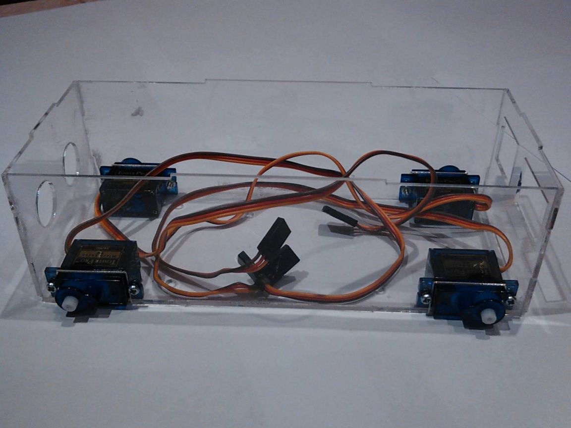
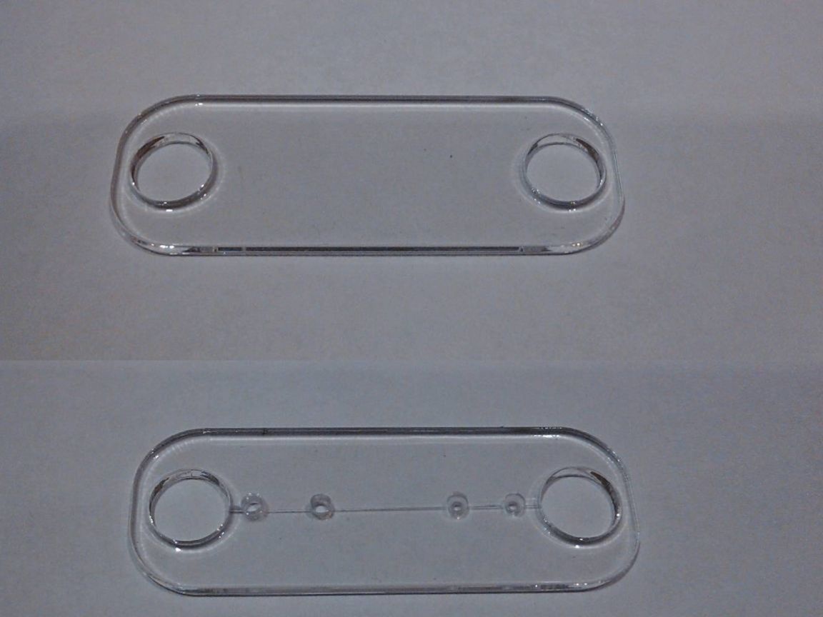
To make the robot body, you need a transparent plexiglass 1.5 mm thick. The blanks were laser cut according to the drawing developed by the author, which is attached to the article.
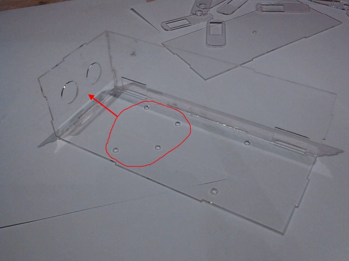
Further, the body elements are glued together, this provides a fairly solid structure for such a robot. When gluing the case, it is very important to ensure that the holes in the bottom are aligned. The side walls must be fixed so that the holes for the exit of the wires are as far as possible to the rear wall. A wide hole on the back is necessary for the output of USB wires. This must be considered during assembly.
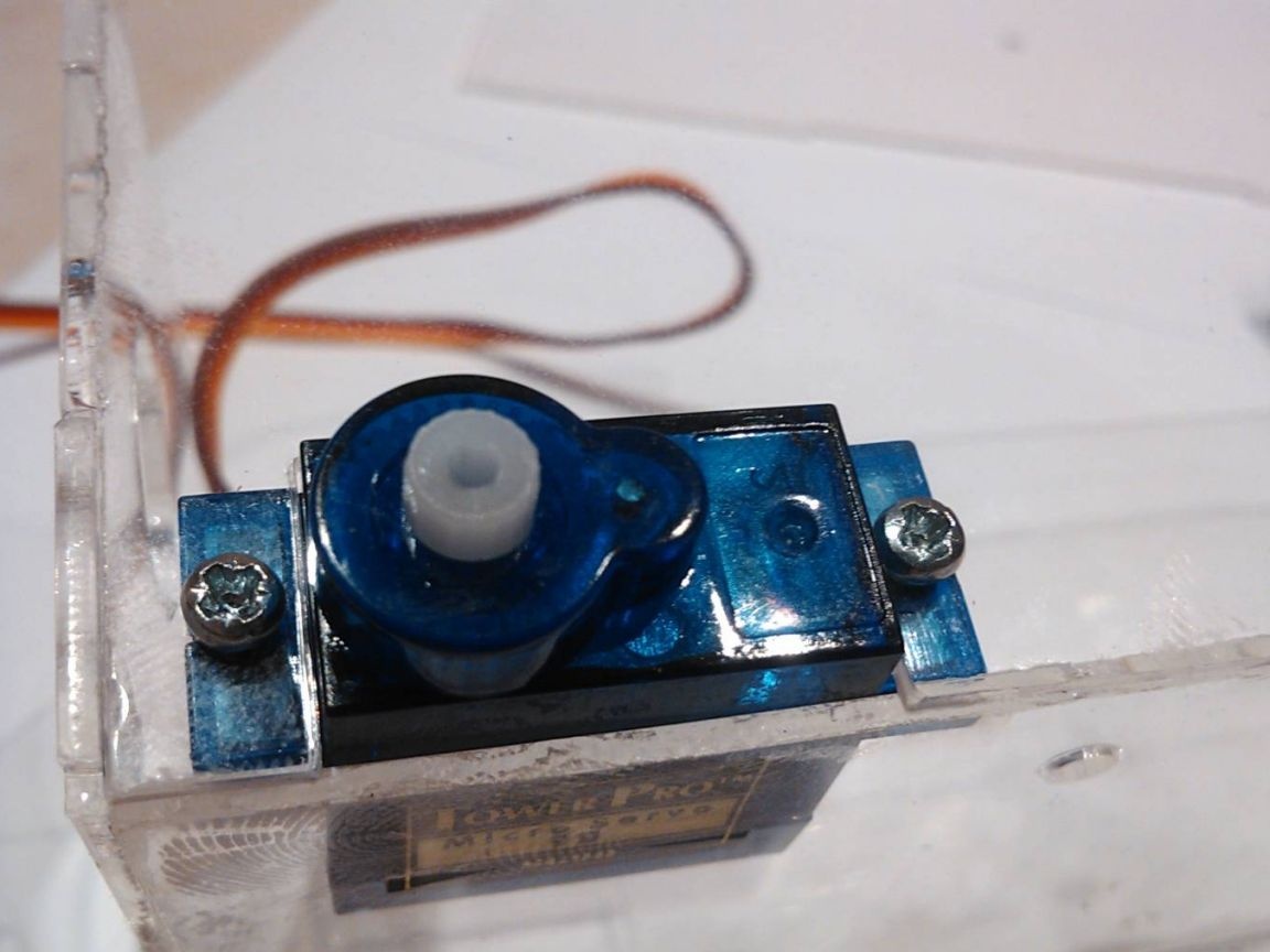
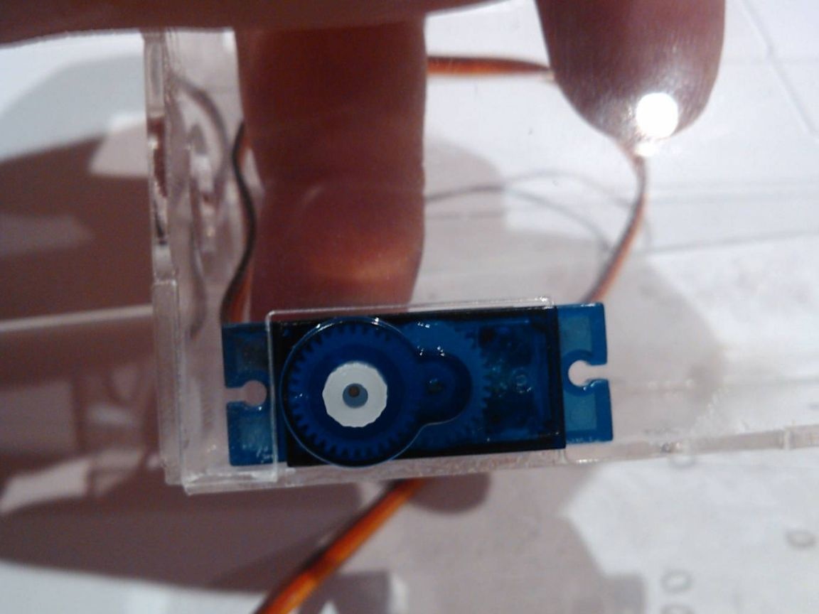
Step Two Fasten servos
To mount the servos, drill holes with a diameter of 2 mm. Engines are mounted with bolts and nuts. The shafts of the front engines should be positioned so that they are closer to the front wall. Well, the shafts of the rear engines should be closer to the rear wall.
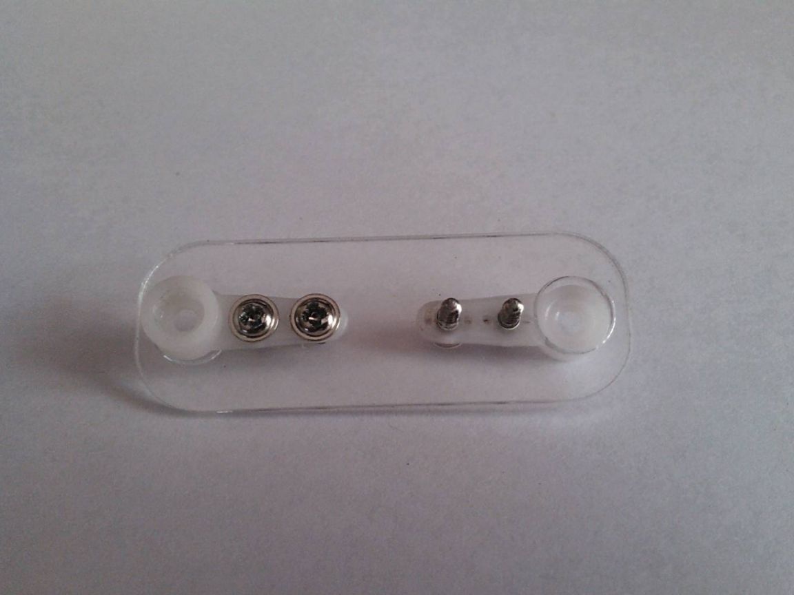
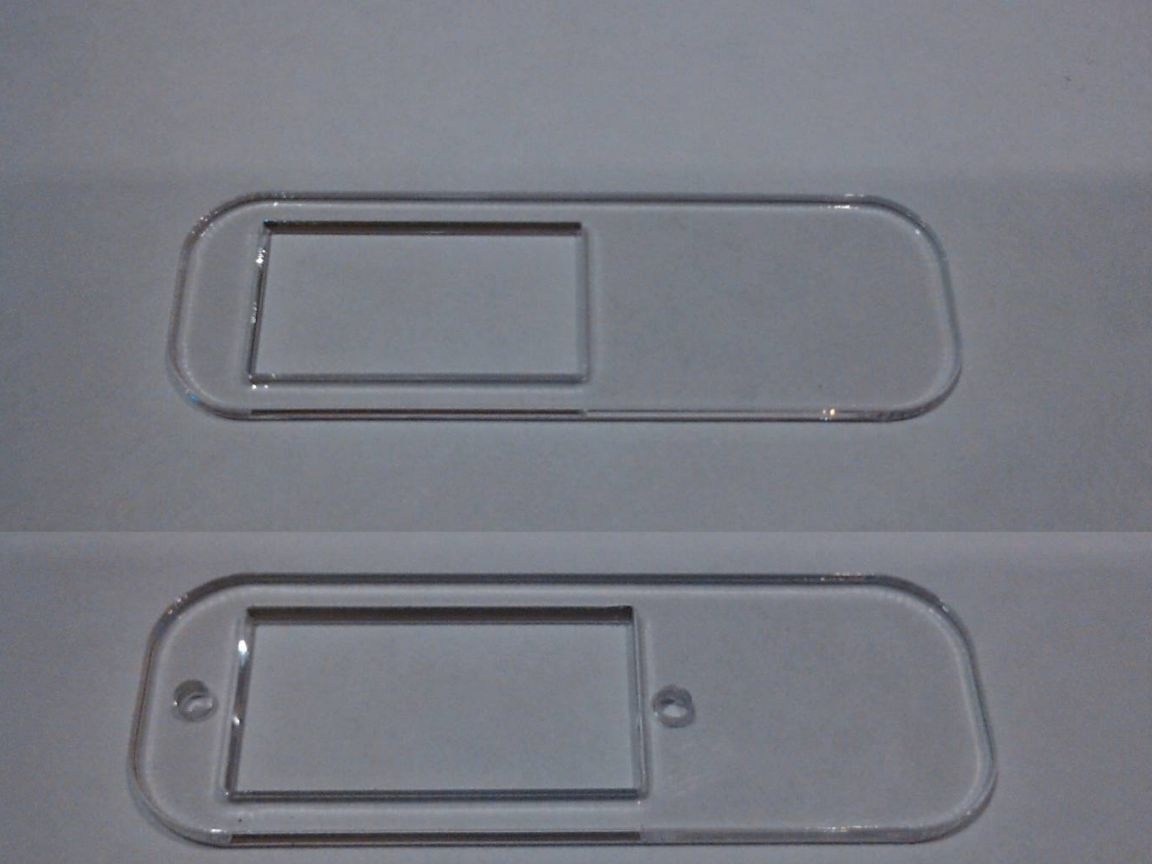
Step Three Assembling Robot Paws
Paws need to be marked in the middle and substituting a rocker for servos, drill holes with a diameter of 1.5 mm. Rocking chairs need to be fixed so that the screw caps are located on the side of the seat.
The holes for mounting the servos should have a diameter of 2 mm. They should be fixed so that their shafts are closer to the narrow edge of the paw.
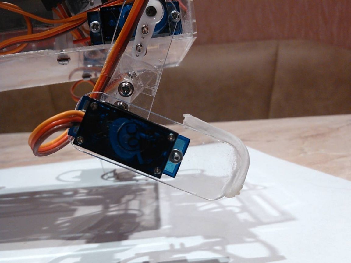
To prevent the paws from slipping when walking the robot, gum must be glued to them.However, it is better not to touch the front of the paws, as in this case the robot may begin to cling to the road and stumble. For these purposes, you can use pieces of sticky rug from the car.
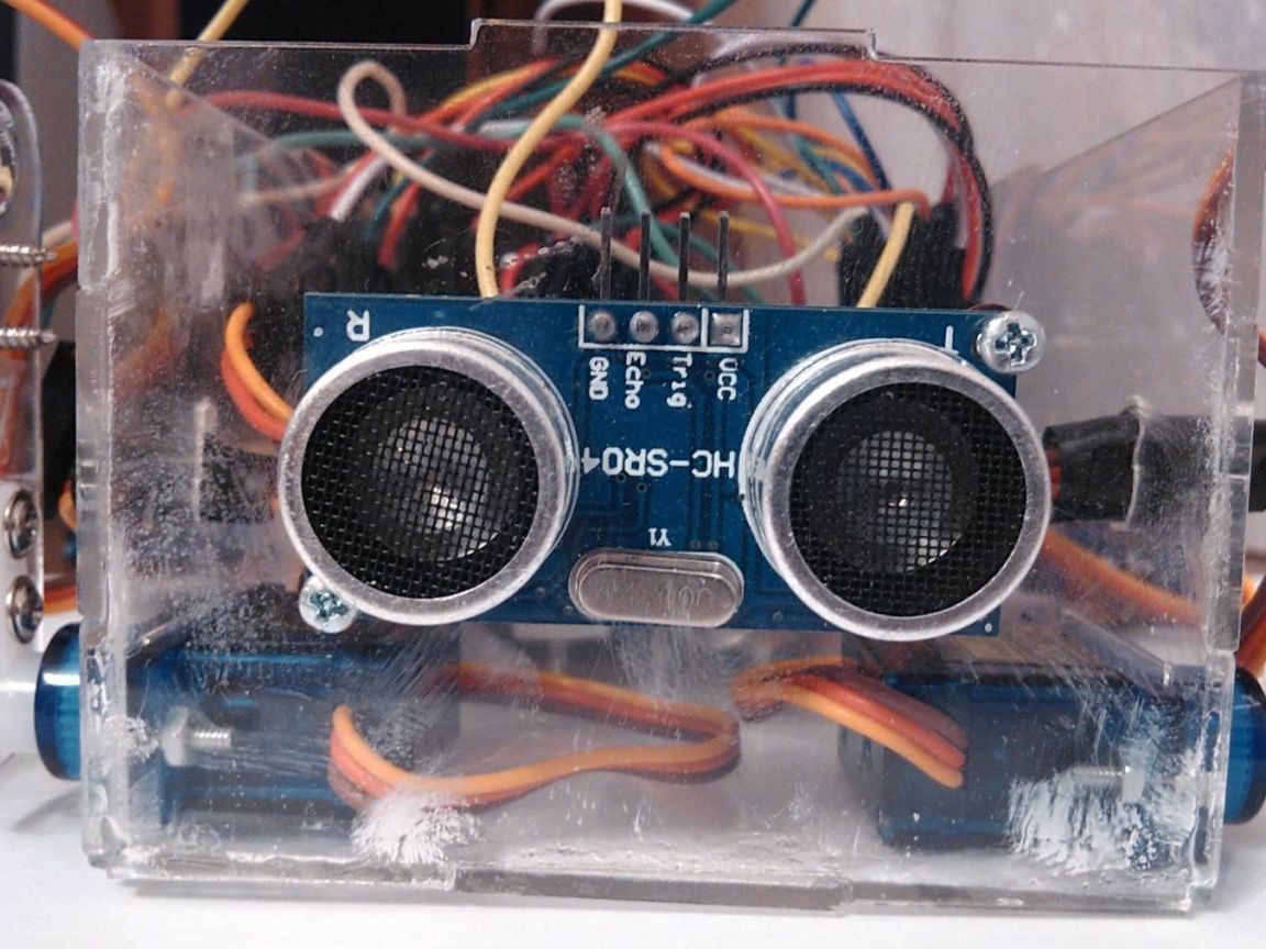
Step Four Setting the rangemeter
To mount an ultrasonic rangemeter, drill holes with a diameter of 2 mm. When installing a rangemeter, its legs should be turned up.
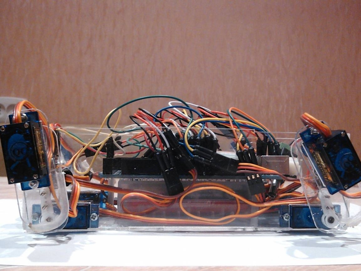
At the same stage, you can install the battery holder. In the case, it should be in the middle. Next, connect the Arduino board and everything is connected to it electronic Components. As a power splitter, part of the breadboard is used.
Step Five Setting up and starting the robot
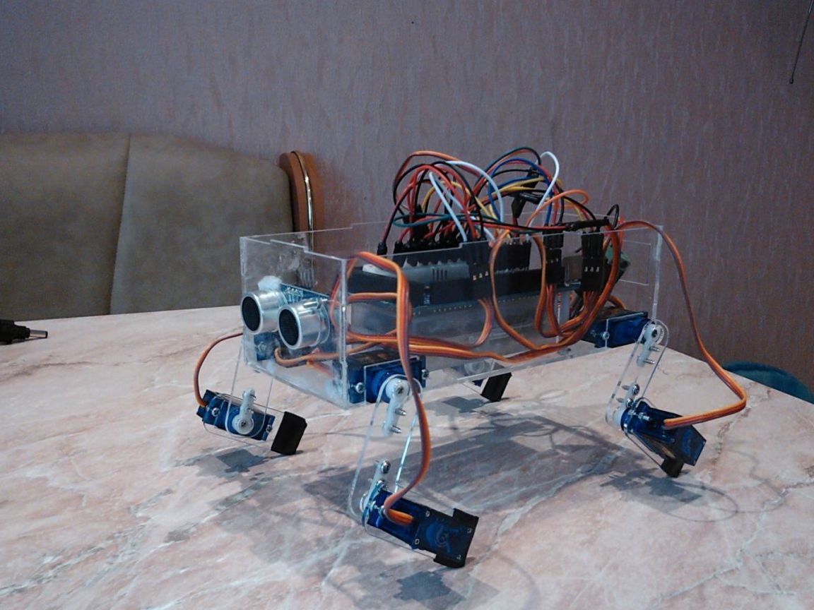
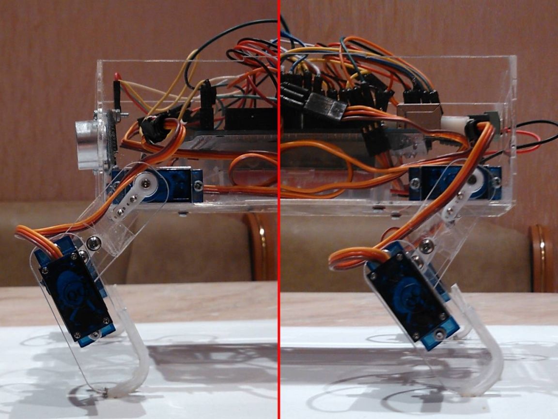
At this stage, you need to calibrate the steps of the robot, paws are installed for this. The biggest problem here is in the rocking chairs, they are attached to the shafts only in certain positions. Servo drives can also differ in degrees of operation. Paws should be tried to set as shown in the photo. Visually, the paws should be in the same positions.
Paws can also be set in the main rack. Next, you need to remember to screw the rockers to the shafts of the servos.
Step Six The software part of the robot
The code is written very simply with detailed comments. Variables are used for each servo, all movements are in the array. So, for example, s1 is the first servo drive, s2 is the second motor and so on. In order to make the code easier to understand, a circuit was attached.
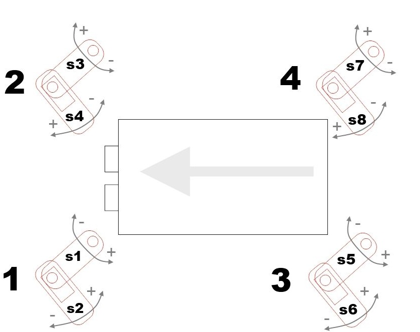
The numbers on the diagram indicate the paws. Moreover, each paw is associated with the engine that moves it. The plus and minus signs indicate the direction in which the paw moves. As the initial angles were used rack angles (s1, s2, s3, etc.). For example, if there is a task to extend the second leg, then you need to change the angle of the servos s3 and s4. This will be reflected in the array as {s1, s2, s3 + 100, s4 + 50, s5, s6, s7, s8}.
That's all, after installing the firmware, the robot is ready for testing. Like many others, it can still be further developed and its capabilities expanded. However, even in such a classic design, the robot behaves very interestingly.