» Electronics »Simple touch button

Simple touch button


The simplest touch device can be assembled on several available parts. Only three transistors, three resistors and one LED, that's all. You can even assemble the circuit by hanging installation, everything will work.

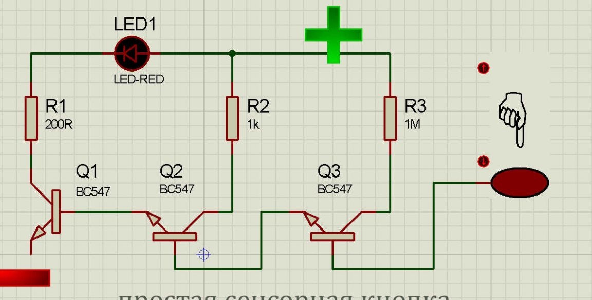
Transistors are any NPN structures: KT315, KT3102 or BC547 or any other. Resistors 0.125-0.25 watts. The LED is of any color, but red is better, since the voltage drop is minimal. Power 5 volts, more less is possible and less too.


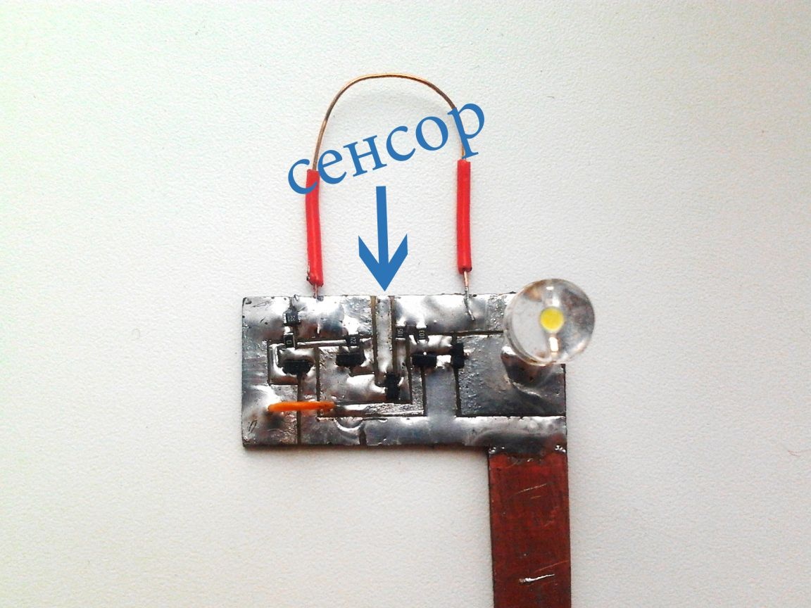
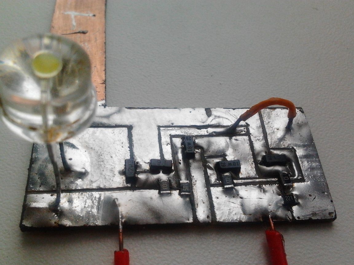
All components were compactly interconnected on a miniature printed circuit board, which can be done simply by cutting out the excess copper with a torch, leaving sharp polygons in this way. Parts used for surface mounting, transistors in sot-26 npn, resistors 0805, jumpers - pieces of wire, instead of them, if you take a large 2512 resistors with zero (conditionally) resistance. The touch device works immediately, without configuration.


Explanation of the operation of the circuit


Touching the base of transistor Q3, you open it with tips, as a result of which a current flows through its CE and 1 MΩ resistor, which opens the next semiconductor Q2, opening it opens Q3, which already controls the LED, opening through its CE flows current, from the minus goes to the cathode LED, and it is already connected to the anode. The 220 Ohm resistor is “current-limiting” here, excess voltage drops on it, which protects the diode from crystal degradation and complete failure of LED1

Application


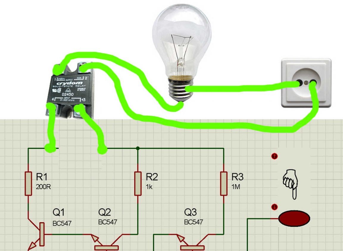
Well, the LED is on at the touch of a finger - so what? But the fact that instead of this LED we put a relay and now we can control almost any load, depending on the characteristics of the relay used. We put a powerful incandescent lamp connected to the network, and in the break of this circuit relay contacts. Now when you press, or rather touch the sensor, the lamp shines.

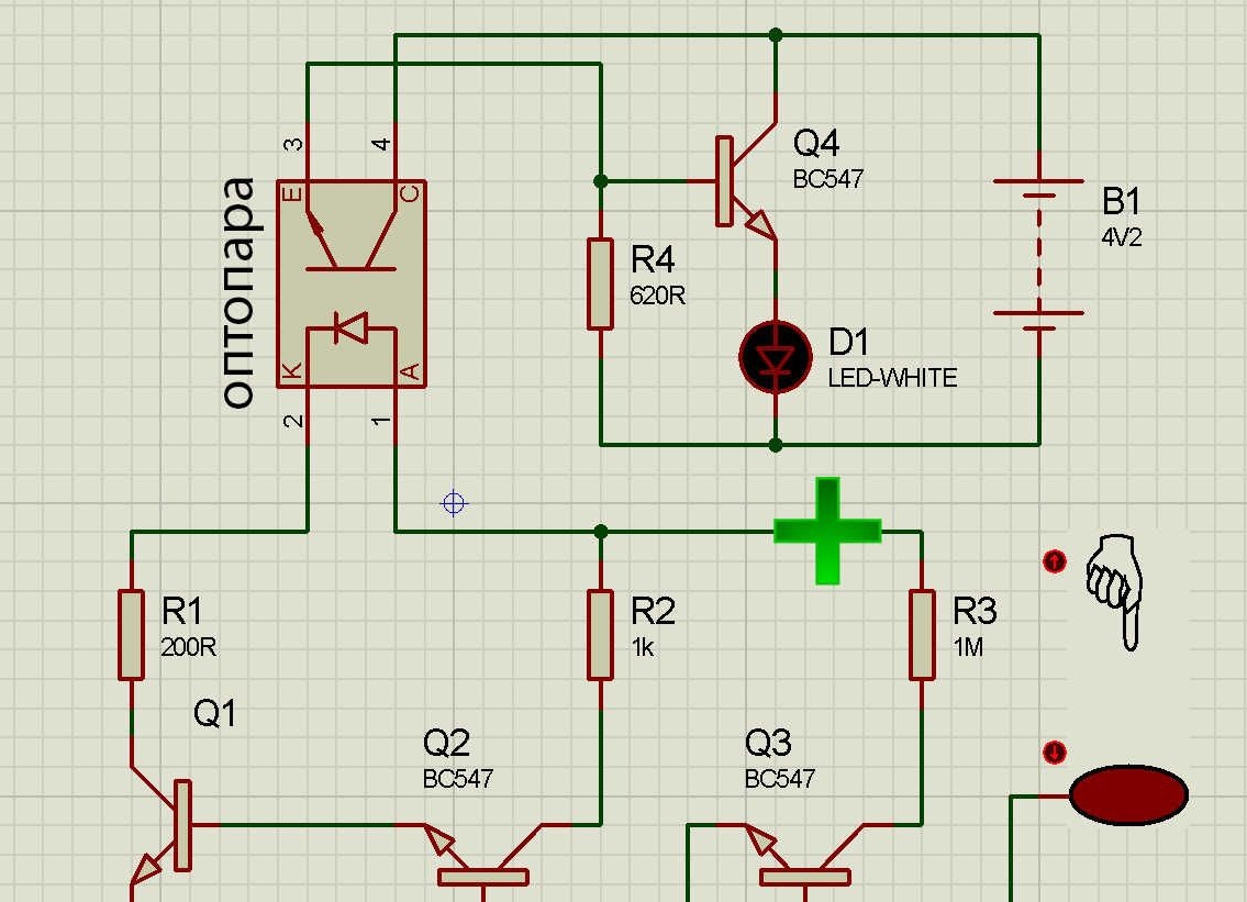
It is also possible to organize switching on / off the load using an optocoupler, if there is no relay, then there will also be galvanic isolation. This beautiful thing consists of an LED and a phototransistor, when the first one is on, it opens the transistor and current can flow through its FE.We include the necessary optocoupler leads in the sensor circuit instead of LED1, and the other two in the gap of the power source and any load. This item can be removed from the phone charges. Take, for example, the PC-17L1.


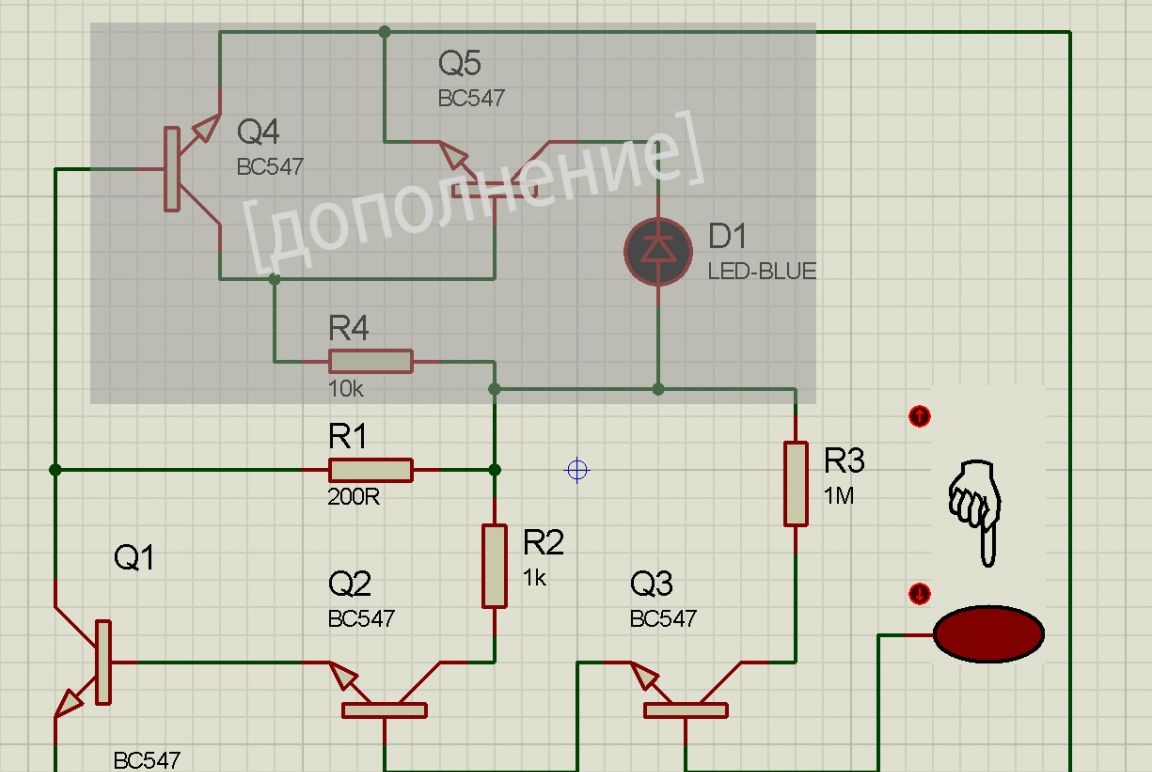
A little lower you see an addition to the main circuit, which shows how to connect an optocoupler to the sensor circuit, one transistor is also added, this is necessary so that you can connect a heavy load, and not just 20 mA LEDs.


Instead of relays and optocouplers, it is possible to use two npn transistors. I did just that, you see the circuit. It works like this: Q5 should always be open, through a 10 kOhm resistor, but through the QE of an open Q4, a minus comes to the Q5 base and because of this it is closed. When you touch the sensor, then the minus goes through open Q1 to the Q4 base and closes it, now nothing prevents Q5 from staying open - the load works, and in my case a powerful 1 Watt LED shines brightly.


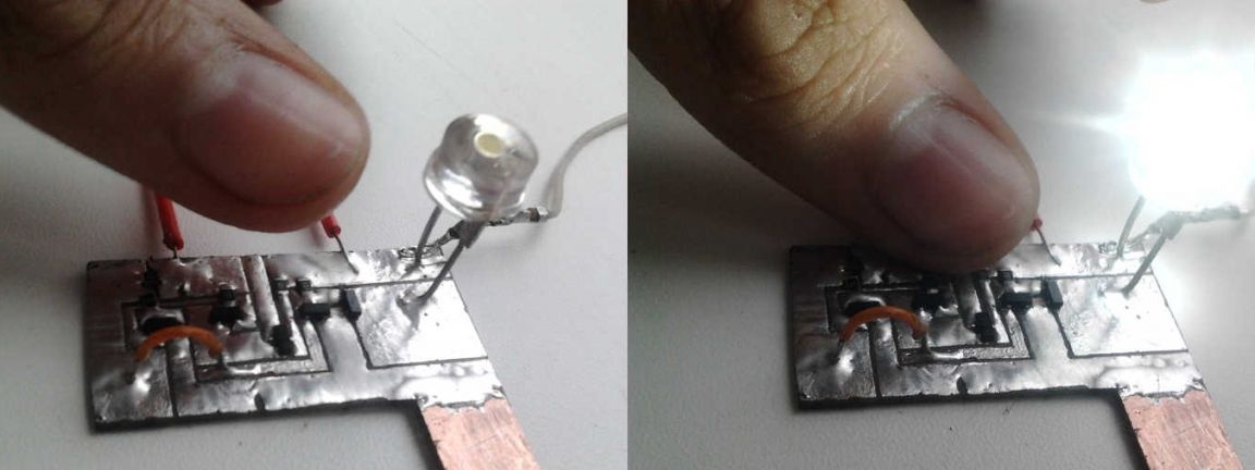
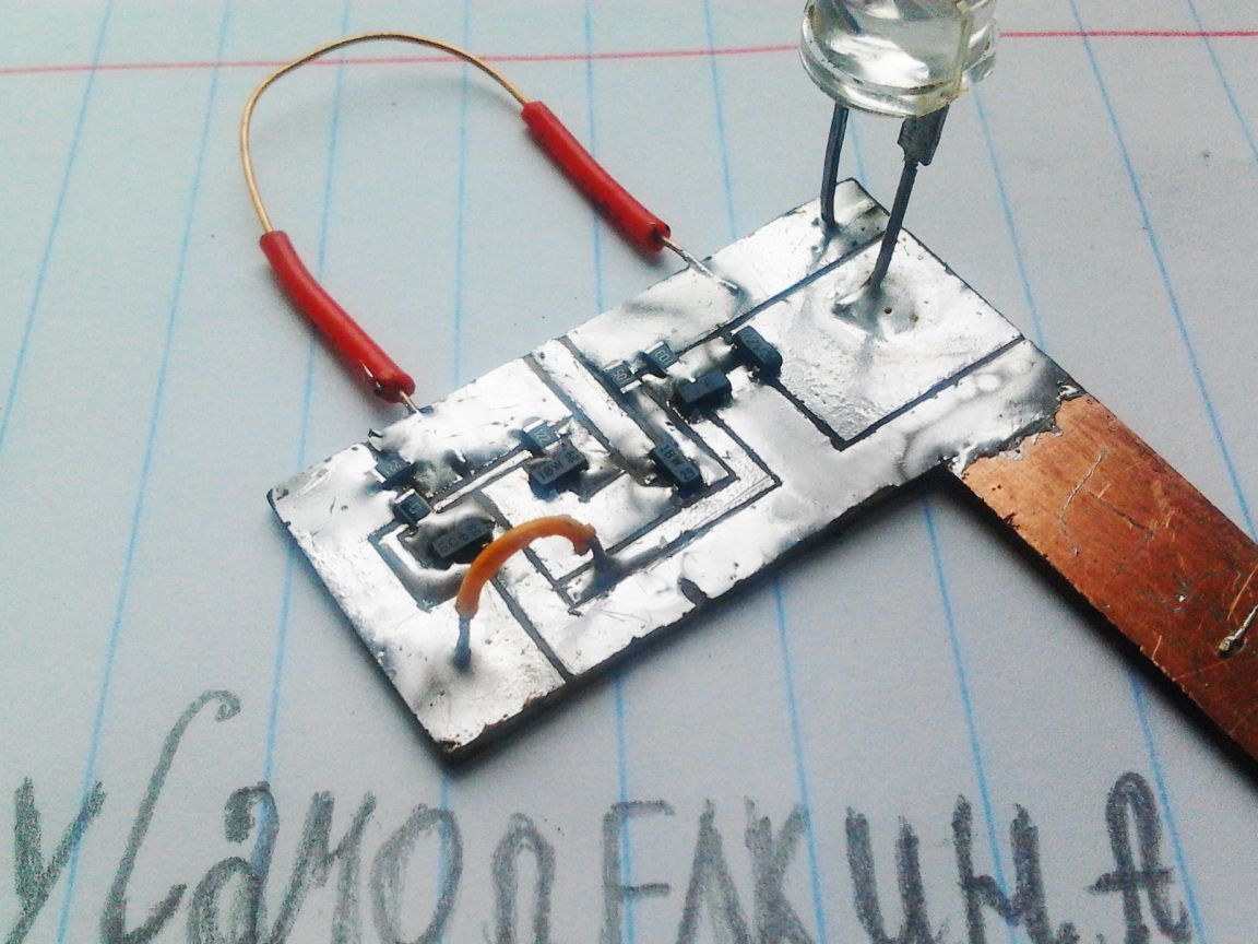
So it looks in assembled condition.


The sensor has no fixation, they touch - it is shining, they are released - it is not shining. If you want to make a fix, just add a trigger to the circuit, for example, on a KM555TM2 chip or any other (you can even implement this on a 555 timer). With the addition of a trigger system, when you touch the sensor, the load will be turned on until the next touch occurs or the power to the circuit disappears.


In practice, this can be used to quickly turn on and off the lighting in the room. Very comfortable, touched a small sensitive area, and the room is lit, a second touch will turn off the light. A small amount of energy will be lost, but this can be neglected.


Comments

The circuit works, but because of its simplicity, it is far from ideal. If the sensor is large, then the circuit may work even when you have not touched it, and if you brush your hair near the sensor with your hand, the LED may also light up. The way out of this situation is simple - a miniature touch sensor.

As already mentioned - the opening of Q3 occurs due to interference, you can see it on video, the LED does not light constantly, but winks at a high frequency, but this is clearly visible when shooting.

The brightness of the working diode is not large, if you only touch the base of the third transistor, but if you touch the plus power, then your body will act in the role of a resistor and transistor Q3 will go into saturation. But in this situation, for some, the meaning of the sensor is lost.

This scheme is very simple and is intended only to understand the principle of operation. electronic components used in serious constructions is not recommended.

Video

10
10
10

Add a comment

    • smilesmilesxaxaokdontknowyahoonea
      bossscratchfoolyesyes-yesaggressivesecret
      sorrydancedance2dance3pardonhelpdrinks
      stopfriendsgoodgoodgoodwhistleswoontongue
      smokeclappingcraydeclarederisivedon-t_mentiondownload
      heatirefullaugh1mdameetingmoskingnegative
      not_ipopcornpunishreadscarescaressearch
      tauntthank_youthisto_clueumnikacuteagree
      badbeeeblack_eyeblum3blushboastboredom
      censoredpleasantrysecret2threatenvictoryyusun_bespectacled
      shokrespektlolprevedwelcomekrutoyya_za
      ya_dobryihelperne_huliganne_othodifludbanclose
25 comments
Quote: Alexey5247
I want to try one more on op-amp and calm down.

Before you poke around like a blind puppy, you need to understand the parameters of electrical conductivity.
Quote: Alexey5247
When touching the surface of the varnish with probes, at a distance of 10 mm between them, the device shows about 1 kOhm.

And the resistance between the probe and the container with varnish? Hardened Epoxy - very good dielectrics. About your liquid varnish is still unclear. Is there any other information besides the words "epoxy varnish"?
Quote: Alexey5247
And further. When the electrodes are immersed in water, the active evolution of gas (hydrogen?) Begins at minus. But, when I connect the minus to the metal tank itself, the boil disappears.

The electrolysis does not stop, but is distributed over the entire contact surface of the water with the tank, and since the current is small, then the bubbles are small.
And why don’t you install a float there. Fell level float closed contacts (or open).
The simplest option: take the KT3107 transistor (or its analog, the parameters are essential: a small reverse current and a large beta) we will call it VT0, tear off the base VT1 from R1, replace R1 with (100 ... 200) kOhm, connect the base VT0 to the common point R1 and R2, emitter VT0 - to the base VT1, collector VT0 - to either end of R3.
As a radiator, you can take a weak (Chinese laser pointer). The receiver is on a photodiode. With the ability to adjust the photodetector in height. Observe physics - angle of incidence = angle of reflection. Do not wipe anything ...
In general, I argue this way: is it possible to make an amplifier of such sensitivity that it works when I pick up the electrodes in my hands? Tell me in which direction to dig. Thanks.
I assembled another circuit on a 555 chip with sensitivity adjustment. It works on water, but not on varnish. Also boiling water in the red. Maybe such schemes on varnish cannot work at all? I want to try one more on op-amp and calm down.
And further. When the electrodes are immersed in water, the active evolution of gas (hydrogen?) Begins at minus. But, when I connect the minus to the metal tank itself, the boil disappears.
Something is wrong. ((
If the varnish resistance of 1 kOhm works on water, then the circuit simply must work.
Hello. He did, as Mr. Pokhmelyov teaches, namely, he closed the HV and the ground, the emitter and collector of both transistors. The relay always tripped. This scheme also works on water, but refuses on varnish. I want to try the op amp circuit, tell me where to find it, thanks.
Can you draw a diagram?
This is already a job. To get started, follow the steps above:
Try to apply the following actions with the power supplied, after each of which check the relay operation:
1. Close the left terminal R2 according to the circuit with the lower terminal R3, for complete happiness - through a resistor of 10 ... 100 kOhm, but it can also be done directly.
2. Close the collector to the VT1 emitter.
3. Close the collector to the VT2 emitter.
What relay, by the way, do you have?
Then the circuit should work. Try to apply the following actions with the power supplied, after each of which check the relay operation:
1. Close the left terminal R2 according to the circuit with the lower terminal R3, for complete happiness - through a resistor of 10 ... 100 kOhm, but it can also be done directly.
2. Close the collector to the VT1 emitter.
3. Close the collector to the VT2 emitter.
What relay, by the way, do you have?
Can you draw a diagram? I'm not good at electronics. I will be very grateful.
When touching the surface of the varnish with probes, at a distance of 10 mm between them, the device shows about 1 kOhm.
An optical sensor was just standing on the automated line for transistor sealing with a compound. The emitter stood at an angle to the surface of the liquid compound. On the opposite side was a photodetector. As soon as the bath was filled (up to a certain level), a beam reflected from the surface fell into the photodetector. Compound supply shutdown worked ... It was a very long time ago.
Quote: Alexey5247
I put together a water level control circuit, as in the diagram, it doesn’t work on varnish. Apparently, there is not enough conductivity of the varnish.
Turn on a 1 MΩ variable resistor between E1 and the common wire and, twisting it, determine the response threshold, if there is something like this, then you can poke between these points with constant resistors. This circuit has a rather large input current, to control a liquid with low electrical conductivity, it is necessary to increase the input resistance by applying a field pole or op-amp in the repeater mode at the input.
when dipsticks are immersed in varnish, it shows numbers
And what is the resistance when the distance between the probes, for example, is 1 cm?
Good day to all.The fact is that I am very limited in space. It seems to me that this type of sensor is the best solution for me. I just need to choose one that is able to work with great resistance to varnish. Sticking varnish is not a problem. I plan to make the electrode block removable and periodically wash it.
At the expense of the capacitive, there were also thoughts, but I have not a great depth, about 30 mm, and the level needs to be maintained within 10 mm. It seems to me that the capacitive sensor will not work for such a difference. I would be very grateful if someone would give me a diagram.
PS. The Chinese multimeter, when the probes are immersed in the varnish, shows the numbers, which I judge that the varnish is conductive. Thanks.
Hanging base in the air - not good!
Or capacitive.
Varnish, it will stick to the electrodes and dry ... And there will be no contact. Here you can use non-contact - an ultrasonic sensor or infrared (optical).
Hello. There is a need to control the level of epoxy varnish in a small container (about 300 ml). The varnish is conductive, but has a lot of resistance. I put together a water level control circuit, as in the diagram, it doesn’t work on varnish. Apparently, there is not enough conductivity of the varnish. Can your circuit work with my varnish?
Supply voltage source, light source and switch.
I’m greeting. Not on the topic) tell me if it’s not difficult. How can I make sure that the light turns on when I open the box?)

We advise you to read:

Hand it for the smartphone ...