

I suggest an option e cigarettes that can be made in home conditions, including an evaporator (atomizer) of its own design, using available materials and tools.
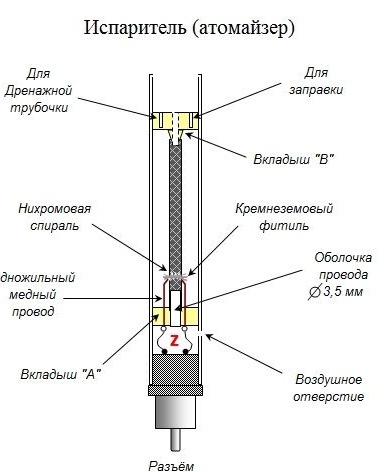
This vaporizer has been serving me “faithfully” for two years now. Schematically, it should look like this.
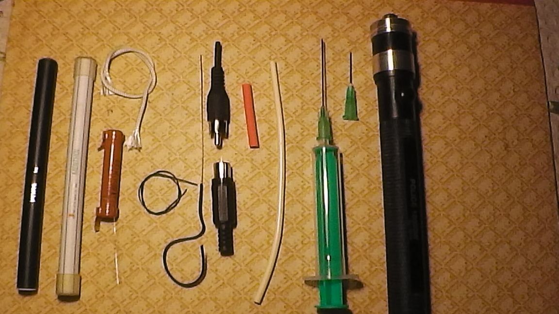
Tools and materials
-Used disposable cigarette "Pons"
-Used disposable cigarette "UXLITE"
- Silica cord diameter = 2 mm.
-Nichrome wire diameter = 0.15 mm.
- Single core copper wire diameter = 0.5 mm.
- Soft stranded wire
-Set of connectors "Tulip"
- Flashlight housing for two finger batteries
- Four "AA" batteries 1.2 v, 1700 ... 2800 mA (two in operation, two in charging)
-Shrink tube diameter = 4 mm.
- Cable sheath (cambric) diameter = 3.5 mm.
- Ruler (vernier caliper)
- Medical syringe with two needles with a diameter of 1 mm
-Wooden toothpick (round - diameter = 2.5 mm.)
-Can hacksaw for metal
- Files (files): flat and round
-Soldering iron, solder, phosphoric acid
-Drills with a diameter of 1.5 ... 2 mm. and 8 mm.
Step 1. Disassemble the Pons disposable cigarette. We remove both plugs and squeeze "offal" from the side of the LED.
Step 2. Remove the synthetic winterizer, battery, processor board and leave only what we need.
Step 3. Remove the decorative sticker, since we will need exactly a transparent case. Remains of glue on the body can easily be washed off with diesel fuel or vegetable oil.
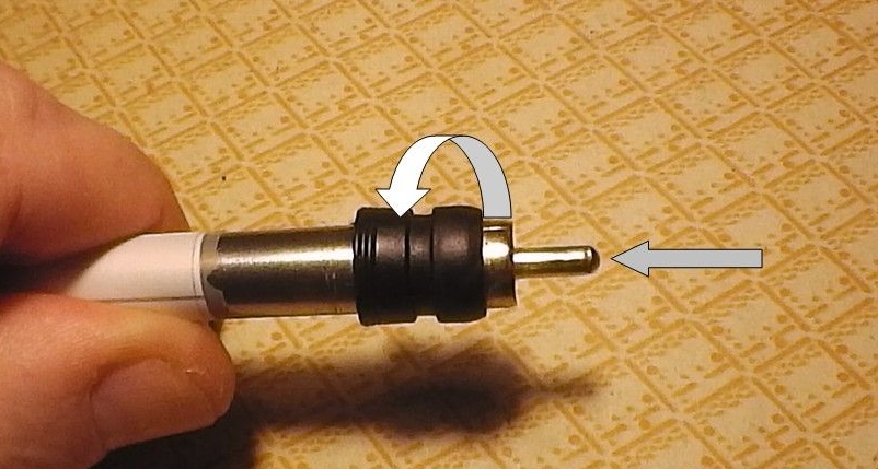
Step 4. We make a tool for planting the Tulip connector into the evaporator body. The case of the UXLITE cigarette is made of stainless steel. Sharpen the edge with a file.
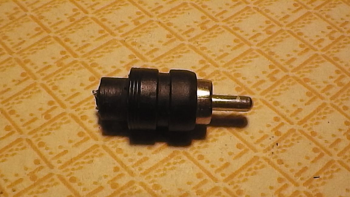
Step 5. By rotating the connector and pressure, we cut out a cylindrical section on it. The diameters of both cases are the same, so it will be inserted symmetrically into the atomizer body and will look neat.
Step 6. We cut the cable strands, separate them to the sides and solder them.
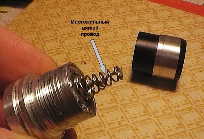
Step 7. We disassemble the main part of the evaporator - a silica wick and a nichrome spiral. "Native" is designed for a voltage of 4 volts, but we need 2.2 V. The wick itself is also a bit thin, designed to work with a synthetic winterizer.
Step 8. Make a heater. For a voltage of 2.2 v, the working section of nichrome with a diameter of 0.15 mm. should be 22 mm. (+/- 1 mm.). It should be borne in mind that with lengthening the amount of steam will be less and vice versa.
It is undesirable to shorten nichrome too much - there will be a smack of burning.Also, the length of nichrome depends on the diameter of the wire. The indicated values are obtained empirically, as optimal.
Copper-nichrome compounds can be made by crimping, but I prefer soldering with phosphoric acid as a more reliable one.
Step 9. Carefully wrap nichrome on a silica cord, spreading the turns with a syringe needle. Cut to size.
Step 10. We insert a cambric into the central hole of the insert "A", as the base for planting the central braided heat-resistant tube.
Step 11. The material of the liners has good elasticity, so with the help of medical tweezers or a clamp, the spiral conductors are easily pierced by copper.
Step 12. We dress the central heat-resistant tube on the inserted cambric and fill the wick with a spiral into a special cutout.
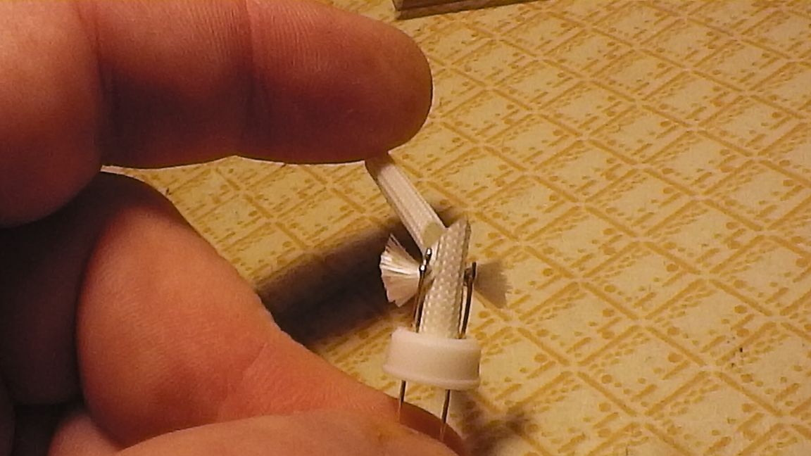
Step 13. We put a heat-shrink tube on the cutout and warm it up to seal. To do this, just hold the area over a hot 60-watt soldering iron, slowly turning along the longitudinal axis.
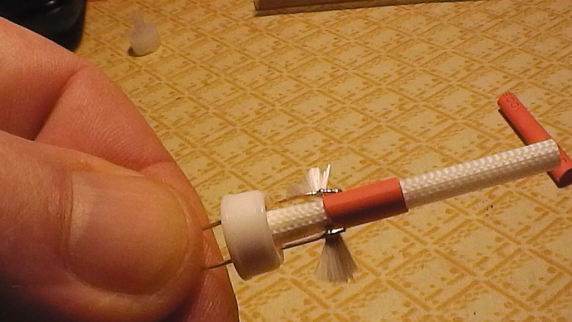
Step 14. Solder the soft conductors to the terminals.
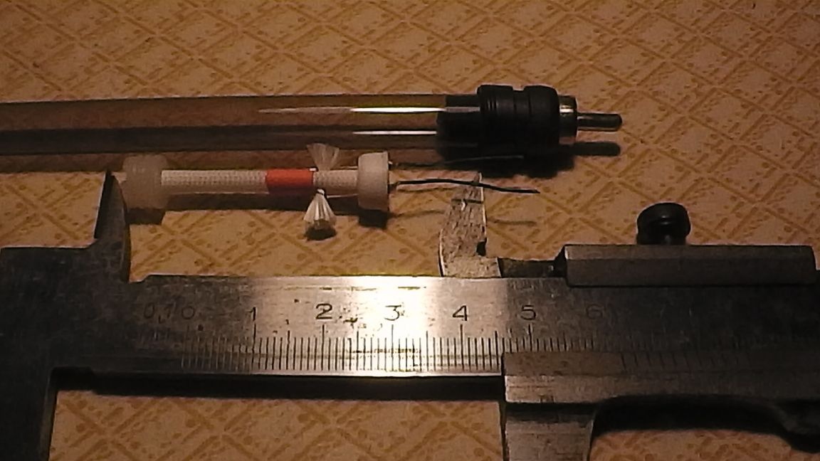
Step 15. Determine the cut-off point, i.e. total length of the evaporator. In our case, 63 mm. We cut the hacksaw blade with metal and carefully process the cut with a file (file).
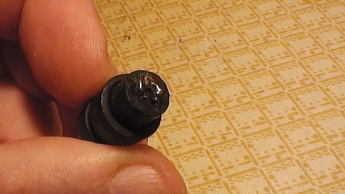
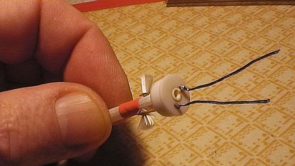
Step 16. After inserting the heater and soldering the soft wires to the connector, we drill an air hole with a diameter of 1.5 ... .2 mm. near the liner.
Step 17. Carefully insert the insert "B" and the connector "Tulip". So that it fits tightly into the case, if necessary, wrap the cylindrical part with a coil of black electrical tape (adhesive tape) before insertion.
As the tip of the mouthpiece, you can use: 1. A decorative plug by drilling a hole in the center with the same drill. 2. Use the cap from the UXLITE cigarette by cutting a hole in the center.
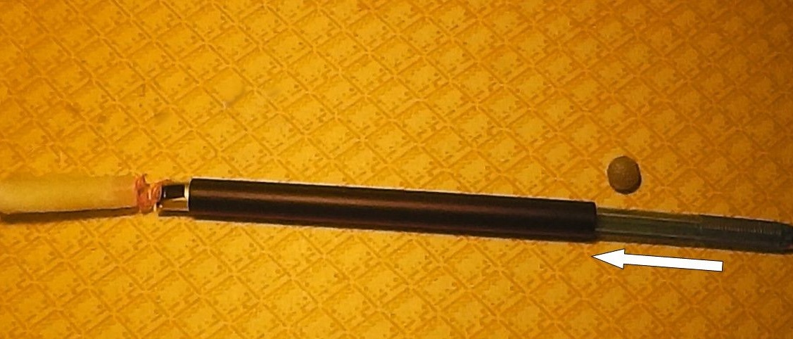
Step 18. The atomizer is ready. Now redo the flashlight body. In this model, the reflector and LED were mounted on the disk from a durable capron, tightly planted in the recess of the duralumin tip.
The diameter of the "Tulip" (mother) is 8.3 mm. So I drilled a hole of 8 mm. and "dispersed" it with a round file to about 8.2 mm. The connector went very tight and sits without any additional fastening.
Step 19. From the spring contact board, we remove all the electronics parts and solder: the “minus” of the connector housing - to the outer ring of the board, and the “plus” - to the extreme ring of the spring. This is best done to reduce current losses, as nickel steel spring has a certain resistance, tangible at a relatively high current device. For the same purpose, it is better to solder the external end part of the board itself.
Of course, it is pressed harder into the sleeve, but it will provide a large contact area in the negative circuit. It is better to “turn over” with a multicore soft wire as well as the spring in the “wrapper” on the back of the flashlight.
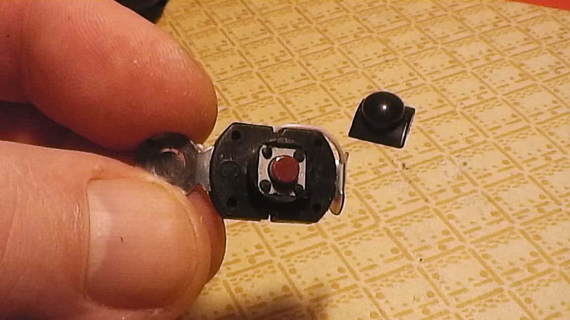
Step 20. We'll have to redo the button as well. she works in a fixed mode. Having removed the details of the latch, I inserted a cut out scarf with a button from the old VCR instead.
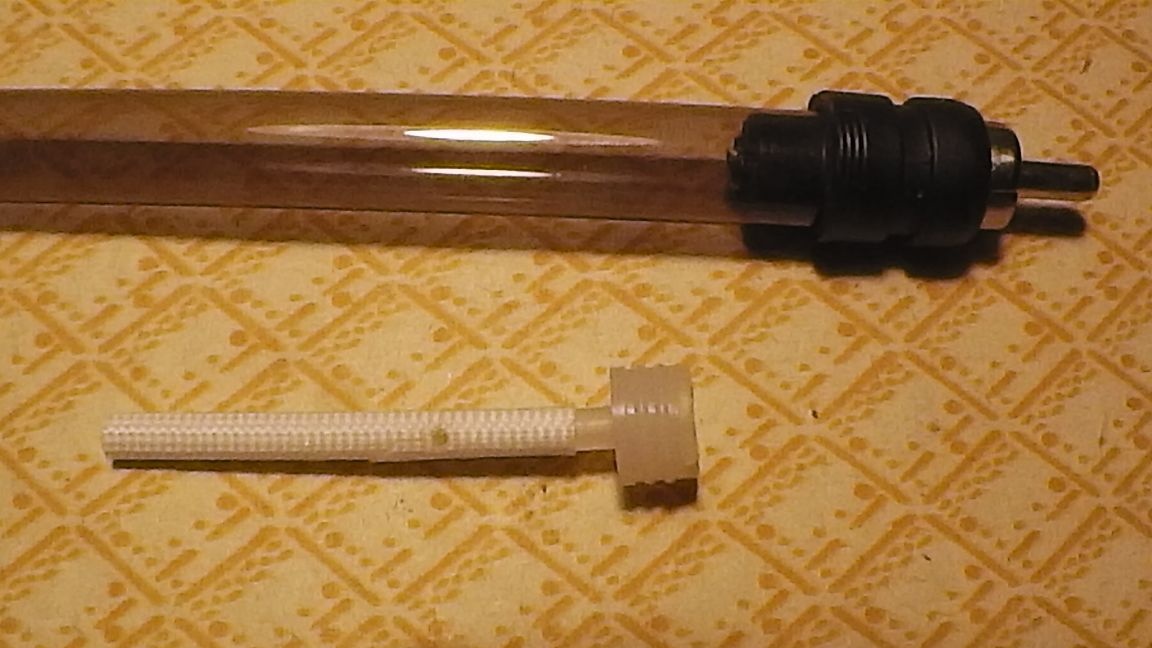
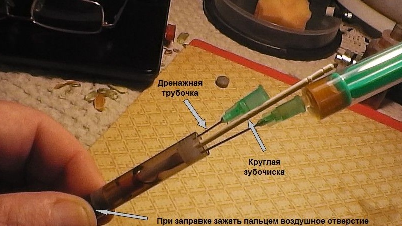
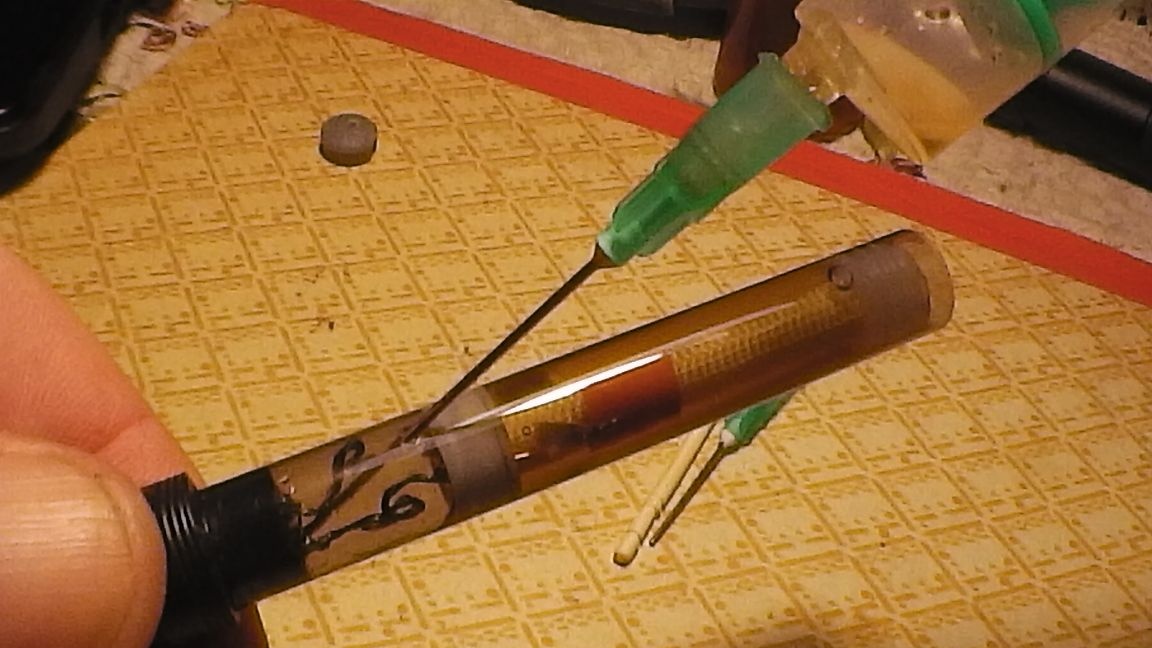
Step 21. Before refueling: insert a drainage tube - a shortened syringe needle (for air outlet) with a minimum tip exit from the insert, insert a round toothpick into the central hole of the insert.
In the remaining small hole - a syringe with liquid and slowly filling the atomizer. During refueling, be sure to (!) Pinch the side air hole with your finger to prevent liquid from entering the air channel.
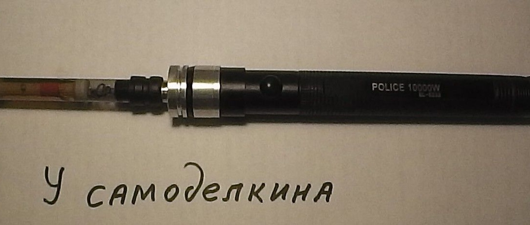
Step 22. Insert the charged batteries, atomizer ...
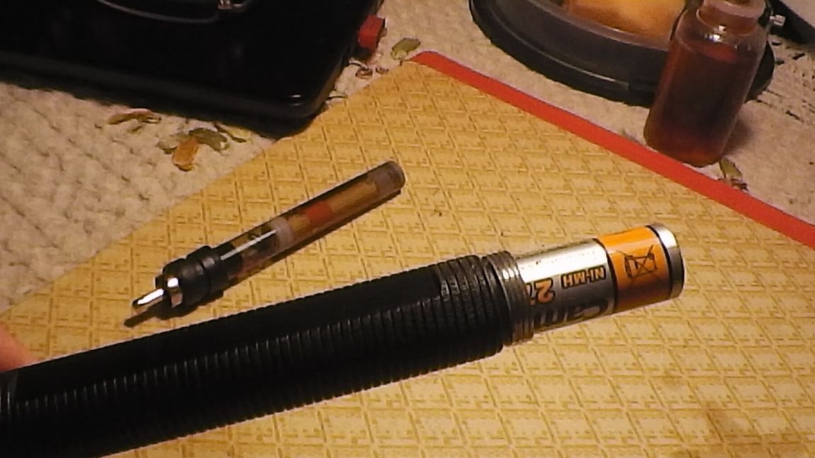
... and "smoke" to your health!
Conclusion
With careful manufacture and assembly, fluid leakage is excluded without sintepon. When there is no air in the main compartment (at full charge), fluid does not flow into the “Z” compartment through the wick holes.
A small leak begins to appear only when the liquid level drops below half of the “F” section, when a certain amount of air is formed in the main compartment.
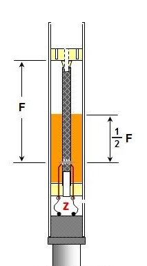
If you do not allow a decrease in the indicated liquid level (monitor it and refuel more often), then the atomizer can constantly be almost dry. If for some reason you “missed” and a little liquid leaked into the “Z” compartment, it can easily be sucked out through the air hole and returned to the vial with liquid for the next refueling.
From both needles I grind off a pointed beveled area, both for safety reasons and the convenience of suctioning the liquid. For aesthetic reasons, I cut a funnel-shaped bell on the flashlight body on a lathe.