
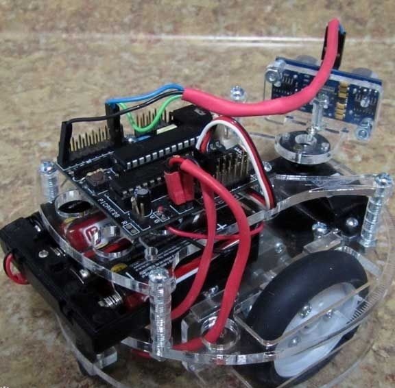
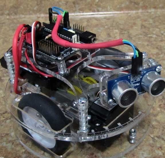
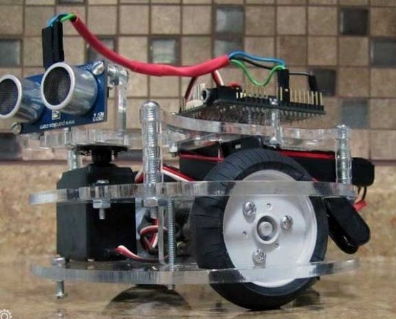
The main feature of this robot is that it is able to circumvent any obstacles. For better and easier adjustment of the robot on its deck there is a scale with an angle of up to 90 degrees. The platform size of the robot is 5 inches, it is also equipped with a sonar.
As for the power source, various combinations can be used here, batteries with a regulator can be used.
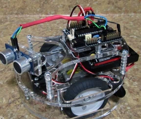
During the tests robot showed excellent results both in a straight line and on an inclined surface. It can perform a variety of functions and can be equipped with a variety of components.
Cutouts can be seen on the top mast of the robot, they are needed to receive sound pulses. There are infrared sensors on the robot, they must be the same.
The author used Tamiya 70097 as a motor for the robot. As for the wheels, they were taken from Tamiya 70145. In addition, you can use a micro or standard servo with an adapter.
Materials and tools for the manufacture of the robot:
- laser-cut robot parts;
- shrink tubes, wires, connectors;
- bolts 41.25 "# 6-32 (they can be bought at hardware stores);
- 2.75 "# 4-40 bolts;
- 42 "# 6-32 bolts;
- 4.5 "# 4-40 bolts;
- one servo drive and all components for it (micro, but standard is best);
- infrared sensor or sonar (in this case PING);
- motor type Tamiya 70097;
- wheels of Tamiya 70145;
- microcontroller Arduino (in this case, Picaxe 28x1 is used).
To reduce soldering to a minimum, an advanced servo drive can be used. Thus, it will be possible to avoid soldering two contacts on each motor. Also, motors can be connected via crimp connectors, then you can completely forget about soldering. But for better work of the robot, it is recommended to reliably solder the contacts.
For these purposes, you still need to stock up with a soldering iron, multimeter, screwdrivers and so on.
Robot assembly process:
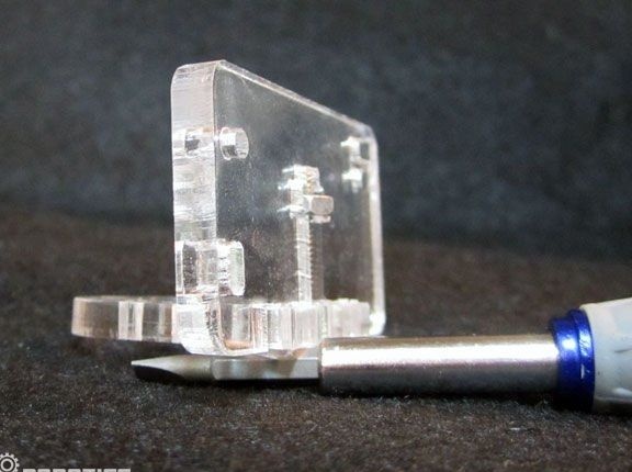
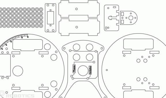
Step one. Cut out the main elements of the body
First of all, using a laser, you need to cut out the main elements of the robot body. For these purposes, you must use the drawings attached to the article.
Step Two We study electronic robot circuit
In the picture below you can see how all the elements of the robot are connected. The PICAXE controller and the Tamiya 70097 engine were taken as an example. After installing the firmware and connecting the robot, it will immediately start working as it should.
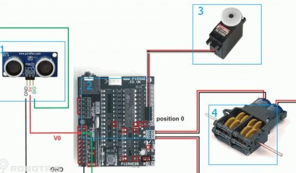
Under the number 1 in the picture is marked a Parallax PING sonar. Under number 2 is the Parallax PING board. The number 3 denotes the standard servomotor, and the number 4 Tamiya 70097 motor.
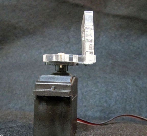
Step Three Robot eye assembly
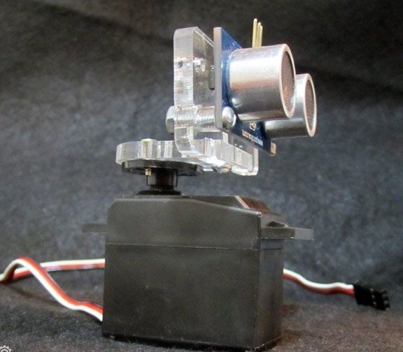
The assembly of the robot begins with the most interesting, from the assembly of the sonar. To install it, 1 .75 "bolts, 2 .5" bolts, 2 gaskets, and three nuts will be required. The assembly is assembled very simply, the plastic platform is attached to the servomotor, and sensors are installed on it, that is, the "eyes" of the robot. Thus, he will be able to turn them and look around.
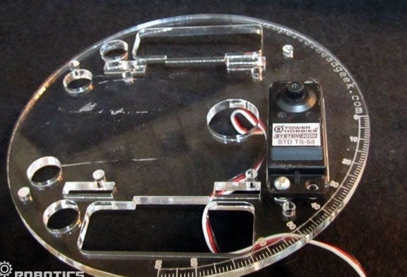
Step Four Install the servomotor
The servomotor must be securely mounted on the upper deck at the indicated location. For these purposes, you will need bolts with nuts. 2 .5 "in size. In the picture you can see how the installed engine will look.
At the same stage, you need to attach the microcontroller to the carrier board. For this you will need 1.75 "screws, gaskets and nuts.
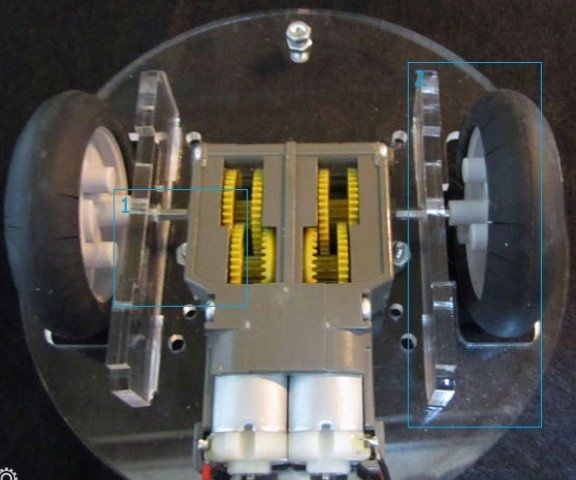
Step Five Putting the lower deck
The engine, together with the uprights and wheels, needs to be attached as one integral element to the lower deck of the robot. For these purposes, you need to find those bolts and nuts that come with the engine. More bolts with nuts must be installed at both ends of the platform. For quiet purposes you need to use bolts and nuts of size 2 .5 ".
In the picture you can see how all the elements are attached to the deck of the robot.
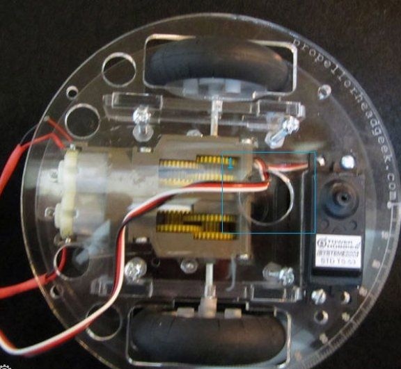
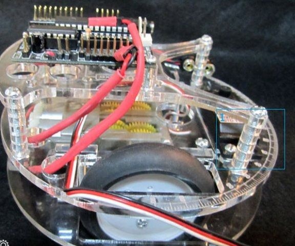
Step Six Connect the decks
Now you need to connect the two decks together. For these purposes, bolts with nuts of 41.25 "are used. Under the number 1, you can see the bolt 1.25".
The wire of the servomotor must be led out through the hole in the platform.
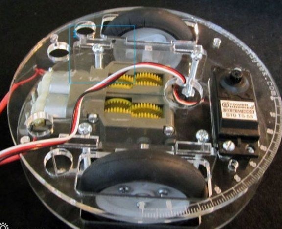
Seventh step. Installing a media card
The carrier board is attached to the upper deck of the robot. For these purposes, you will need bolts with 41.25 "nuts, as well as 20 gaskets. Alternatively, 1" hexagonal gaskets can be used. With the help of them it will be possible to quickly change the height of the deck to install various types of power sources.
Step Eight. Installation of sonar and servomotor
A match with a sonar is connected to the controller, and it is attached to the shaft of the servomotor motor using special bolts that come with the kit. Well, in conclusion, you need to install a battery, for these purposes you can use tape or glue.
That's all, the robot is ready. After installing the firmware and connecting the power, it will immediately come to life. In the future, the robot will be able to improve or add various new functions.