
Materials and tools for the manufacture of the robot:
- any plastic bottle of 1.5 l;
- an old machine on the control panel;
- set of Arduino Proto Shield;
- software package Arduino Uno;
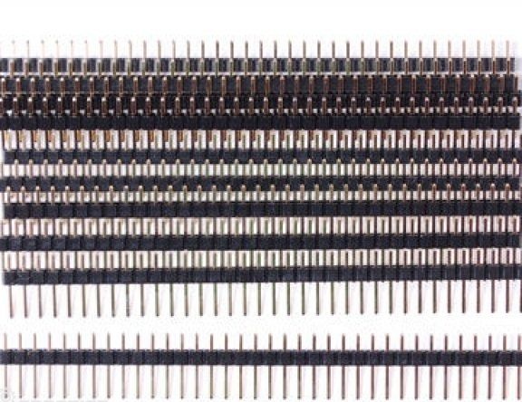
- connecting contacts (set);
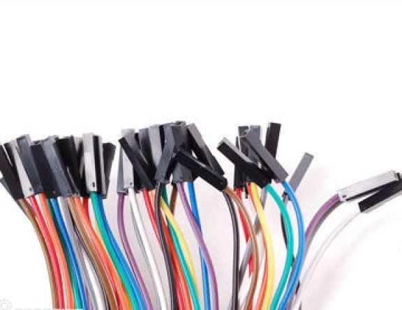
- A set of jumpers of type Female / Female;
- 6 volt solar panel;
- Two Parallax servos (continuous rotation);
- two standard servos of the Parallax 4-6VDC type;
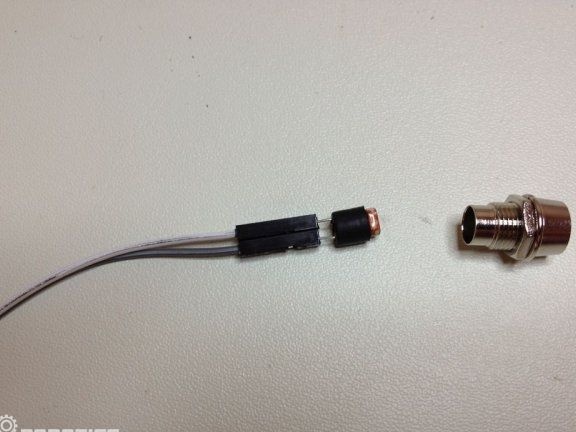
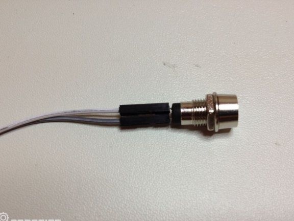
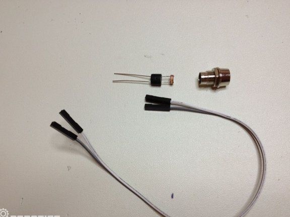
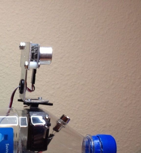
- Collision sensor Parallax Ping Sensor;
- holder for four AA batteries;
- holder for 9V battery;
- four photoresistors;
- four holders for LEDs;
- four resistors per 10K ohms;
- one micro 1A diode 1N4001.
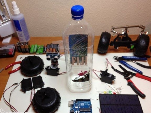
Of the tools you will need: a soldering iron with solder, pliers, dremel, side cutters and another tool.
Robot assembly process:
Step one. Robot brain device
The Arduino Uno microcontroller is best suited for this robot, as it is designed for small projects and programmed using C ++.
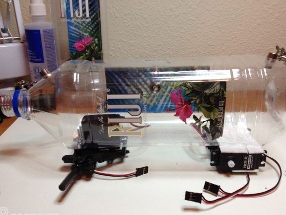
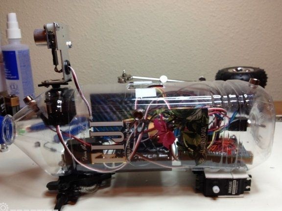
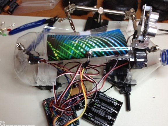
The robot has four servos, one controls the wheels, its task is to rotate the wheels continuously. The second servo is needed in order to control the head of the robot, collision sensors are installed on it. And another servomotor controls the axis of the robot, forcing it to rotate.
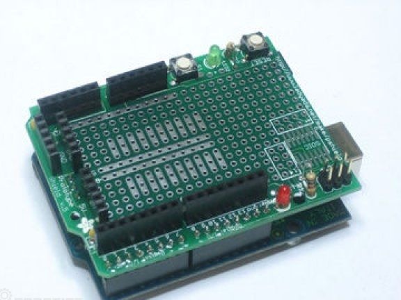
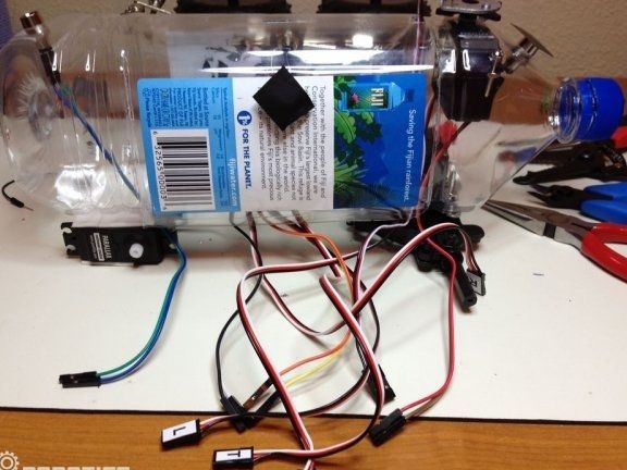
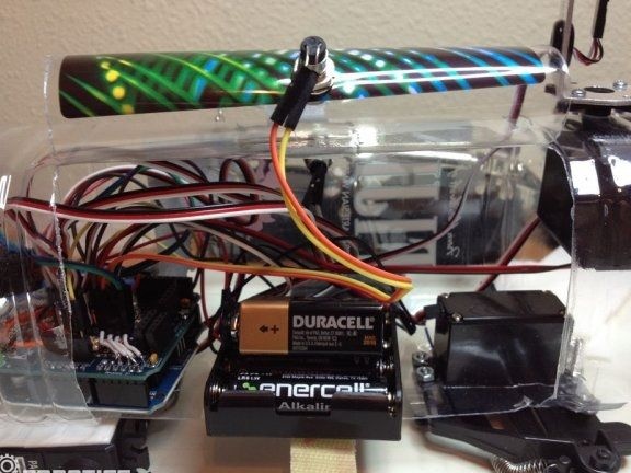
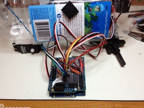
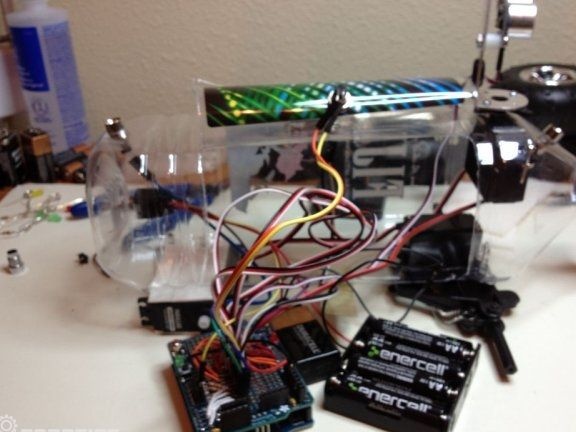
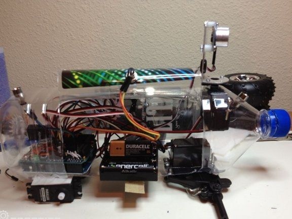
It is important to understand that the Arduino Proto Shield board will be located in the bottle, so you need to make the circuit diagram so that it is convenient to connect and disconnect various sensors, servos and more. For these purposes, the Proto Shield board with all the necessary Adafruit contacts is perfect. Contacts should be soldered to the Proto Shield screen, and all elements should be connected with jumpers.
In the middle part of the board there are two channels that are connected to +5 V and GND. Perpendicular panels can be seen on the right and left sides of these channels. They are needed in order to connect 5 breakaway contacts between perpendicular panels and two channels. From here, the servomotors will receive power, as well as control pulses.
If you look at the photo below, you can see that the connectors that come with the Proto Shield are not soldered to the second side of the digital outputs and to the analog contacts. This must be left as is by soldering the wires directly to the panel.
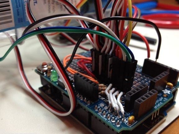
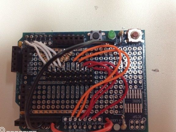
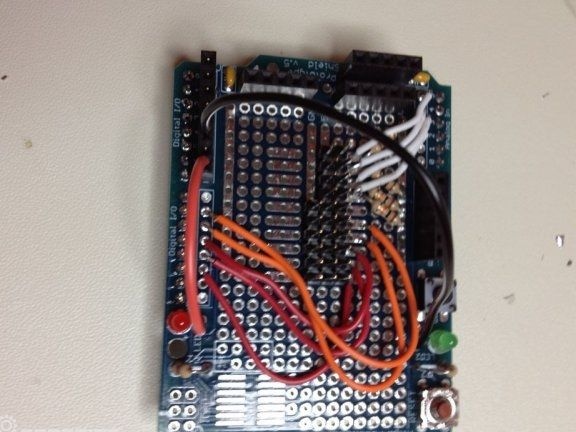
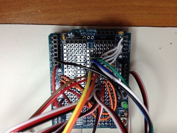
You also need to connect the wires to the PWM outputs (for servo drives), as well as to the analog ones for photo resistors. For each photoresistor, add one 10K resistor.
There are pins 7 and 9 on the Proto board, they need to be connected to the positive pins of the red and green LEDs.
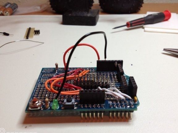
In order for the robot with four servos and Arduino to function normally, two power supplies are needed. The microcontroller requires 9V power. Collision sensors and servos will be powered by four AA batteries; they are connected to a 6V solar panel.
In order to prevent reverse current between the solar panel and the battery, a diode must be installed in the circuit.
Step Two Sensor Preparation
Photoresistors are mounted on the platform using holders. This allows you to quickly remove them during the assembly or refinement of the robot. One end of the female / female jumper is connected to the photoresistor, and the other to the Proto Shield board. Rubber gaskets prevent the risk of a short circuit.

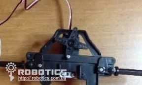
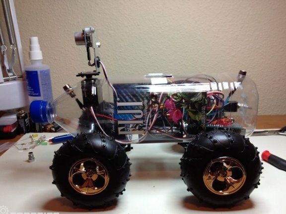
Step Three Chassis assembly
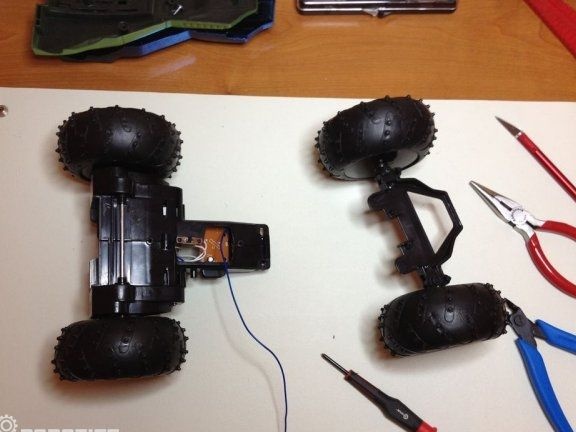
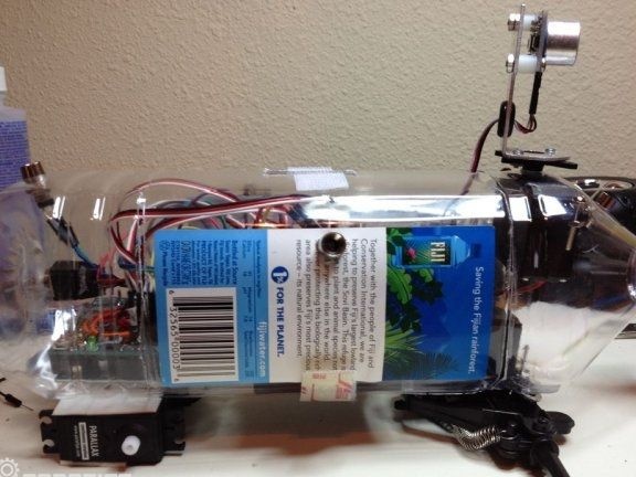
For the manufacture of the chassis will need a baby car on the control panel. It needs to be disassembled, leaving only those elements that are visible in the photo. The front axle will have to be rotated using a servomotor.
Both elements (front and rear axle) are mounted in a plastic bottle, for this, the holes necessary for the size are cut out in it. Well, now it remains only to connect everything as in the photo.

Step Four Programming process
The main task that the robot code must perform is to search for the light source and charge from it. Four photo resistors are used to search for the light source. The program loop should compare where the light is brighter, and then the robot should go to it.
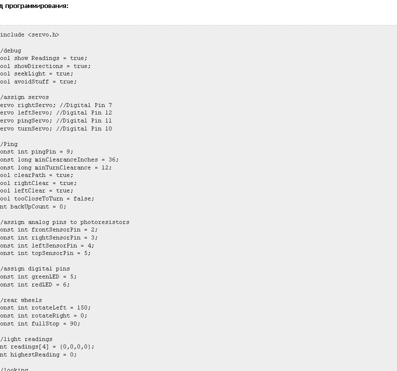
To prevent the robot from crashing, another cycle should check for obstructions every 30 inches. An ultrasonic sensor is used to obtain this information. If the robot detects an obstacle, it must stop, look around and choose the best path.
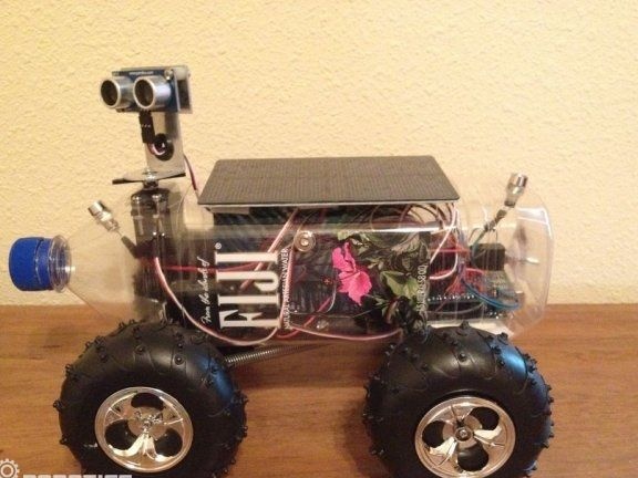
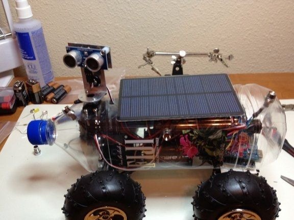
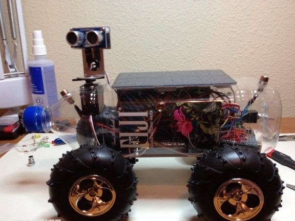
Step Five The final stage of assembly
After the robot is programmed, it can be finally assembled and tested. To test the robot, you need to create several light sources of different brightness in the room, and create obstacles in the way of movement to them. The robot must reach the brightest light source without crashing into obstacles.
Of course, there are many more options in terms of improving the robot. You can add a wide variety of functions to it, here everything depends on the desire and imagination of the master.