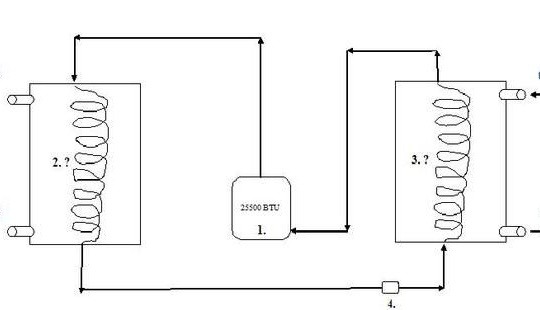
Such a device will be a godsend for owners of cottages and private homes that are not connected to the gas. The main advantage of this method of heating a room over others is that heat pumps consume little energy and are able to heat a room quite efficiently. With such a heat pump, as the author made, there is a partial heating of the house in 2.5 floors and an area of 213 sq. meters.
Two 24,000 BTU compressors are used in the installation, as a result, electricity consumption is about 4 kilowatts per hour, and heat is released at the same time 16-18 kilowatts.
Two compressors are needed in order to increase their service life, as well as reduce the starting currents that occur when turned on.
Materials and tools for manufacturing:
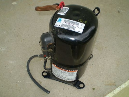
- two compressors;
- thermostatic valve;
- a metal tank to create a capacitor;
- copper pipe to create a coil;
- a plastic barrel to create an evaporator (about 120 l);
- brackets and other fasteners;
- TRV;
- single-phase starting relay and other elements.
Heat pump manufacturing process:
Step one. Compressor installation
The compressor power should be around 25500 BTU. It is attached to the wall as indicated in the picture. For this, L-300mm brackets are used.
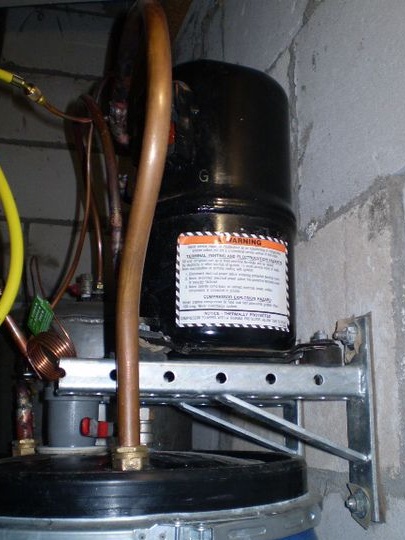
Step Two Capacitor device
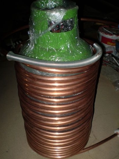
To create a capacitor, you need a stainless steel tank with a capacity of 120 liters. The tank was cut into two parts and then a freon guide coil was inserted into it. After that, the tank was welded back. Also at this stage it will be necessary to weld several technical threaded joints.
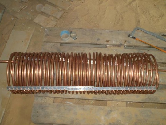
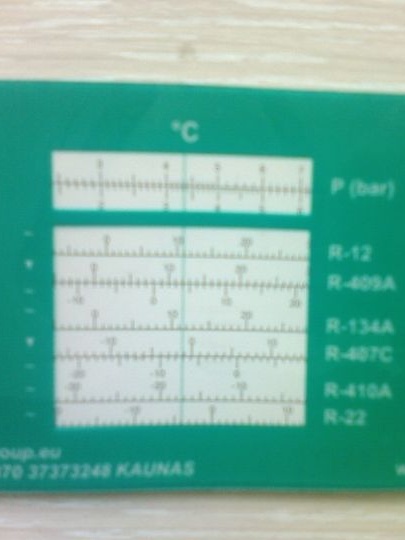
The area of the copper pipe of the coil is calculated using the formula M2 = kW / 0.8 x ∆t.
∆t is the difference in water temperature at the inlet and outlet of the system. The author is 35s-30s = +5 degrees C.
M2 - coil pipe area (square meters).
kW - heat dissipation capacity of the system (with a running compressor) in kW.
0.8 - the coefficient of thermal conductivity of copper / water under the condition of counterflow media.
As a result, the heat exchange area of the coil is about two square meters.
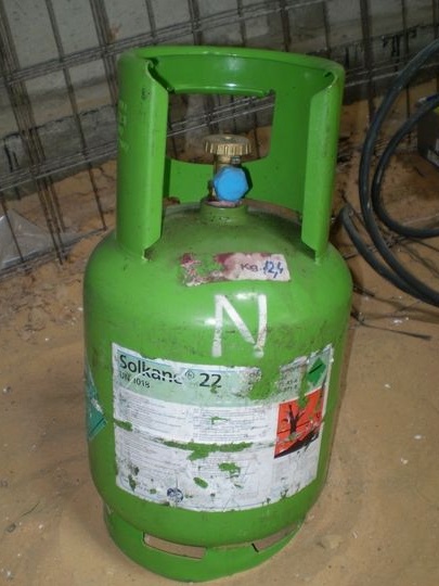
The coil is made of a copper tube, which is wound on any object that is suitable in shape, the author has a gas cylinder. The total length of the pipe was 35 meters. For the structure to be strong, it must be fixed with two aluminum rails and copper wire.
The ends of the coil are displayed using plumbing findings. Instead of a crimp ring, flaxen rope with sealant was used.
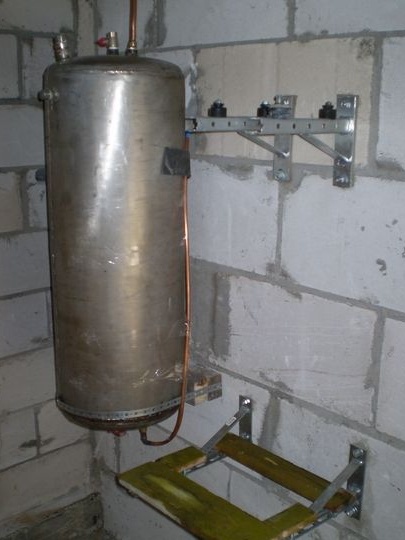
Step ThreeEvaporator device
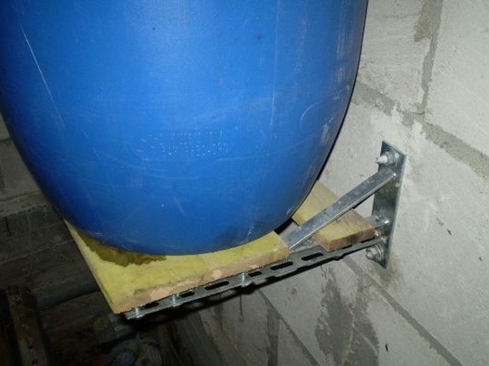
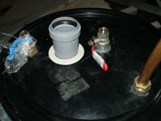
To create an evaporator, you need a plastic barrel of 127 liters with a wide neck. The evaporator is manufactured in the same way as the condenser. That is, you need a copper pipe 25 meters long, from which you need to make a coil.
Such an evaporator is a flooded type. The liquid freon enters through the coil from below, then it evaporates in it and then spreads already in the form of gas, then it moves to the compressor. At the same time, heat transfer improves.
Transitions fit plastic PE 20 * 3/4 ’, from drinking water. Water is supplied and drained through ordinary sewer pipes. Subsequently, the evaporator is mounted on brackets of size L-400mm.
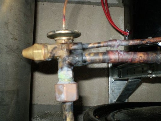
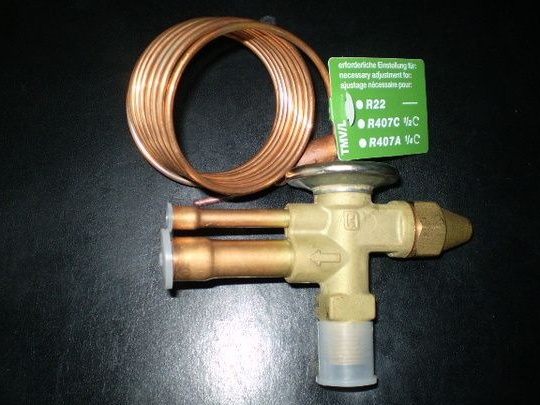
Step Four TRV connection
Expansion valve used by Honeywell. When soldering, you need to be extremely careful, since the expansion joint does not withstand temperatures of more than 100 degrees. Before soldering, it is necessary to wrap the expansion valve with a wet cloth, so cooling will occur.
Step Five Assembly device.
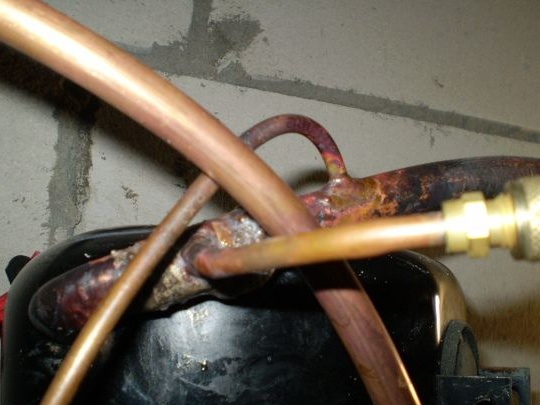
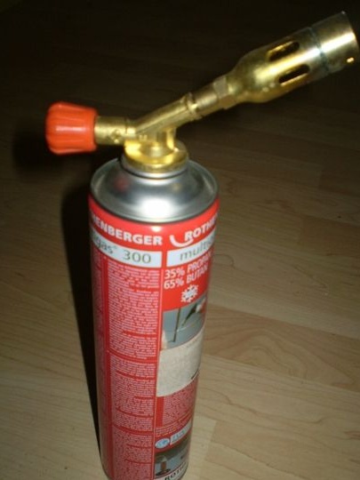
To assemble, you need a Rotenberg Rigid Soldering Kit. You will also need three electrodes with zero silver content and one electrode with a silver content of 40% for soldering on the side of the compressor. As a result, the connection will be vibration resistant.
you must remember to solder the Schroeder filling valve into the system; there must be a nipple on it to connect the hose. It is soldered at the inlet to the compressor. The equalizer inlet pipe is brazed after the evaporator, but before the cylinder. Before soldering, the spool must be unscrewed, as the rubber seal will melt.
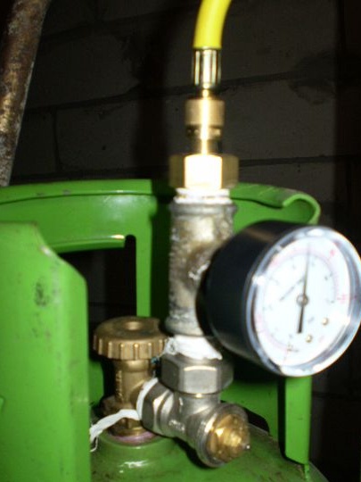
Step Six Freon filling
Before refueling, you need to expel air from the system, for this a certain amount of freon is fed into it to displace it. For refueling, no more than 2 kg of freon will be needed. For refueling you will need a manometer, with it you can monitor the process.
Seventh step. Electronics
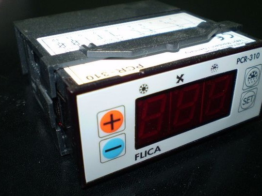
To start the system, a starting relay is necessary, so the starting currents are about 40 A. There must be a fuse, as well as a shield with a DIN rail. You will also need a thermal sensor, with it the system will automatically turn off when a certain temperature is reached.
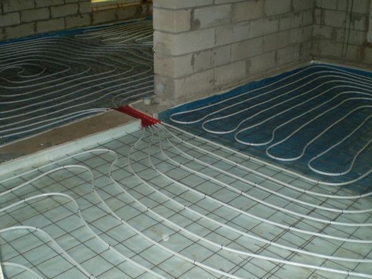
According to the author, immediately after the first launch, the system worked as it should. Now you can connect the heating circuit and conduct heat around the house wherever you need. After that, you will need to make pressure and expansion valves.