
The robot works on the board Arduino. A computer unit is used as a power source.
Materials and tools:
- 6 servomotors;
- acrylic with a thickness of 2 mm (and another small piece with a thickness of 4 mm);
- a tripod (to create a base);
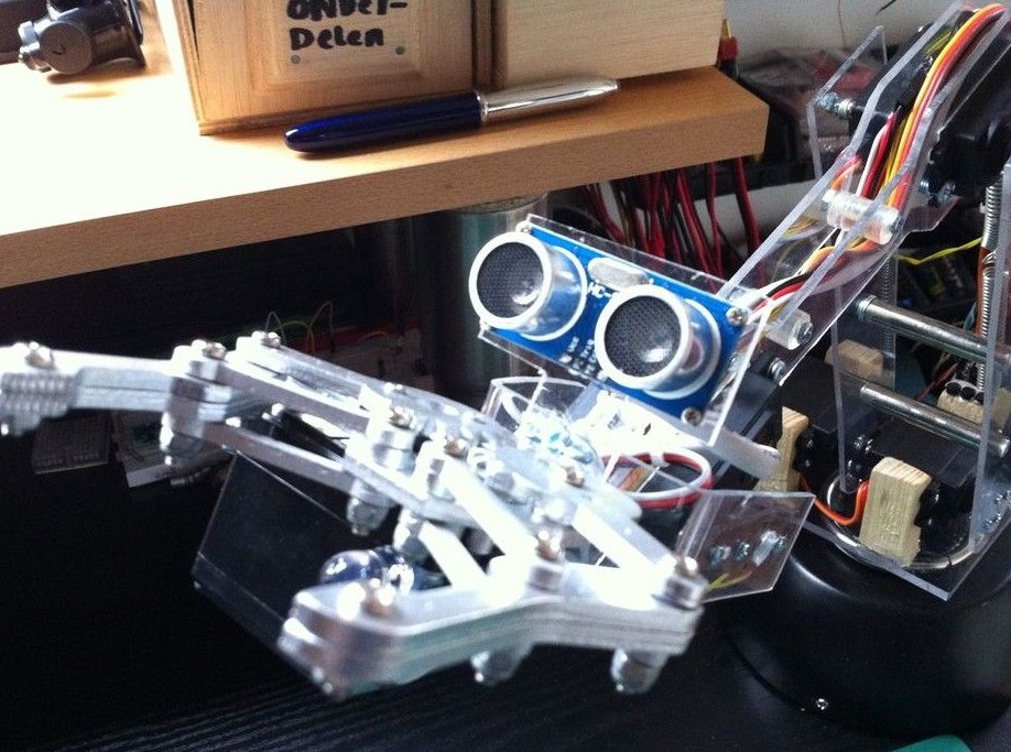
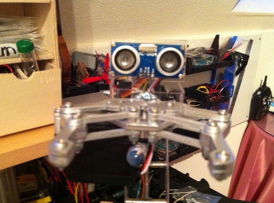
- ultrasonic distance sensor type hc-sr04;
- Arduino Uno controller;
- power controller (manufactured independently);
- power supply from a computer;
- computer (needed for programming Arduino);
- wires, tools and more.
Manufacturing process:
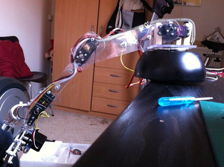
Step one. We assemble the mechanical part of the robot
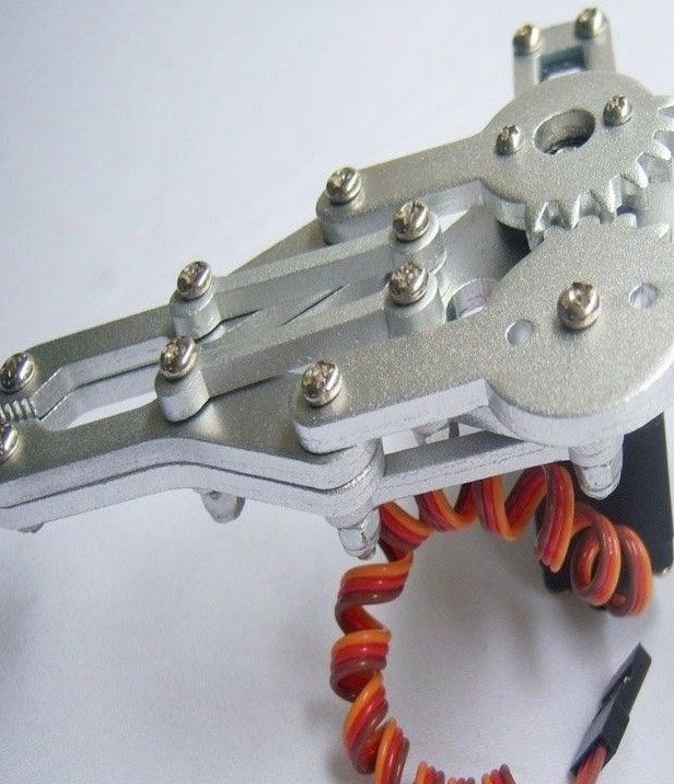
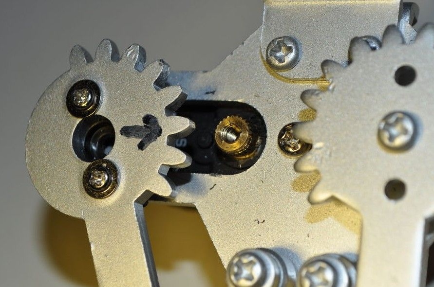
The mechanical part is assembled very simply. Two pieces of acrylic need to be connected using a servomotor. The other two links are connected in a similar way. As for the grip, it is best to buy it online. All elements are fastened with screws.
The length of the first part is about 19 cm, and the second is about 17.5 cm. The front link has a length of 5.5 cm. As for the other elements, their sizes are chosen at personal discretion.
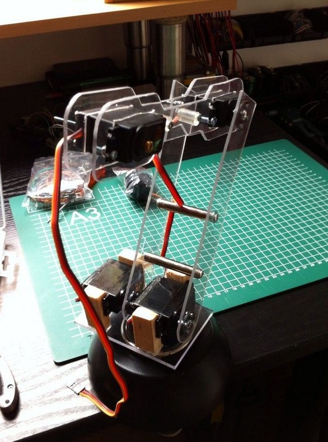
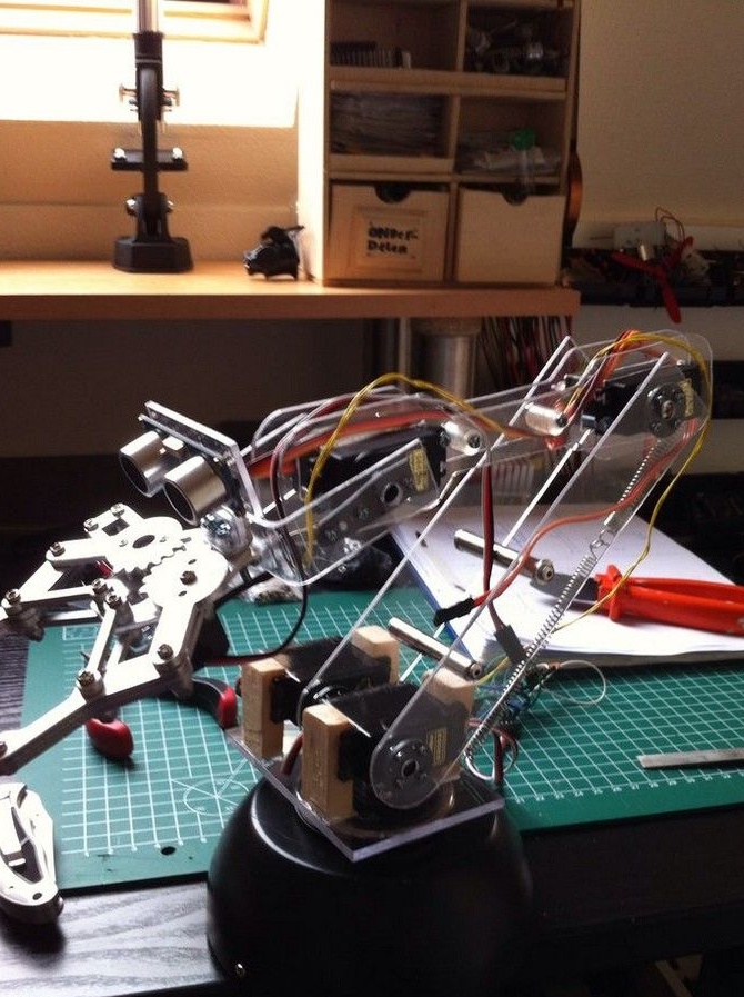
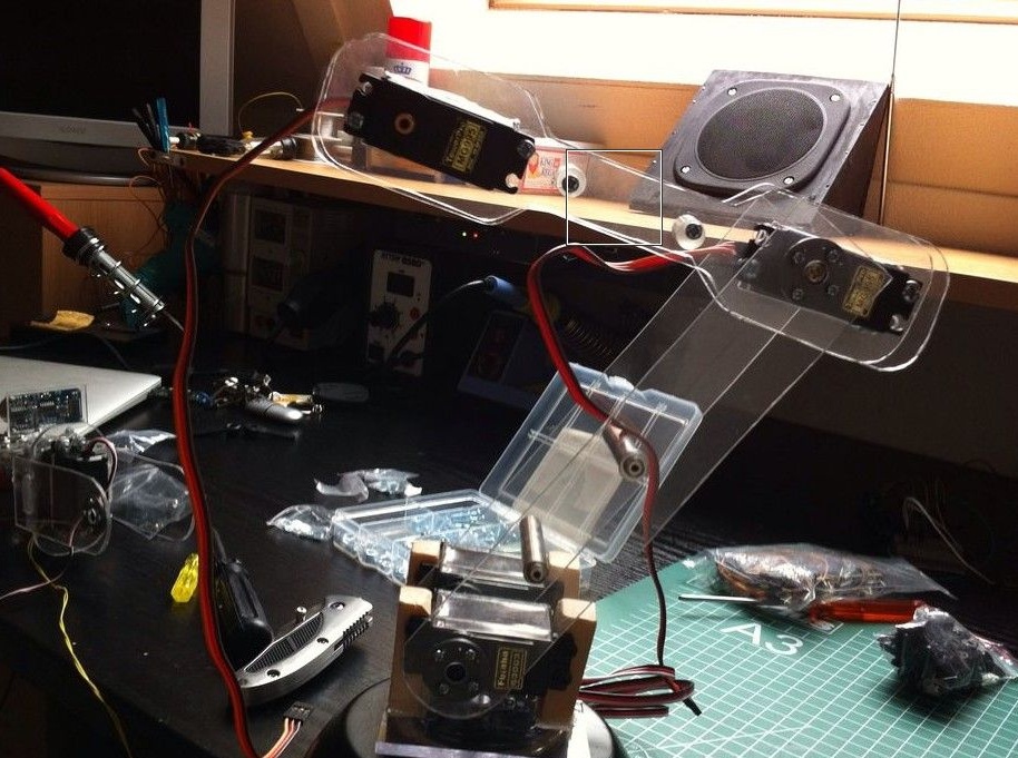
The angle of rotation at the base of the mechanical arm should be 180 degrees, so you need to install a servomotor from below. In our case, it needs to be installed in a disco ball. The robot is already installed on the servomotor.
To install an ultrasonic sensor, you need a piece of acrylic 2 cm thick.
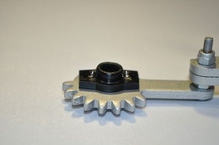
To install the gripper, you will need several screws and a servomotor. You need to take the rocking chair from the servomotor and shorten it until it comes to the grip. Then you can tighten the two small screws. After installation, the servomotor must be turned to the leftmost position and the gripper jaws are brought together.
Now the servomotor is mounted on 4 bolts, while it is important to ensure that it is in the extreme left position and the lips are brought together.
Now the servo can be connected to the board and check if the gripper is working.
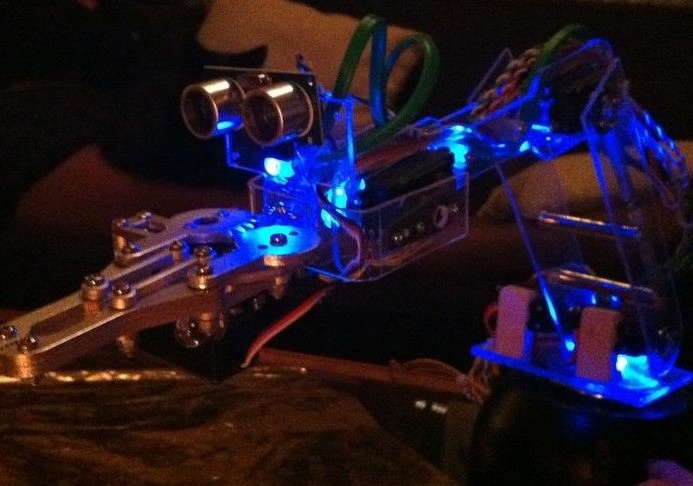
Step Two Robot backlight
To make the robot more interesting, it can be made backlight. This is done with the help of LEDs of various colors.
Step Three Connection e parts
The main controller for the robot is the Arduino board. A computer unit is used as the power source, at its outputs you need to find a voltage of 5 volts. It should be, if you measure the voltage on the red and black wires with a multimeter. This voltage is needed to power the servomotors and distance sensor. The yellow and black wire of the unit already produces 12 volts, they are needed for the Arduino.
For servomotors, you need to make five connectors. We connect 5V to the positive, and negative to the ground. The distance sensor is connected in the same way.
There is also a power LED on the board. A 100 ohm resistor between + 5V and ground is used to connect it.
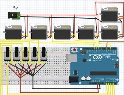
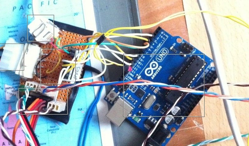
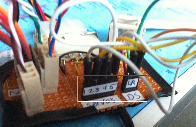
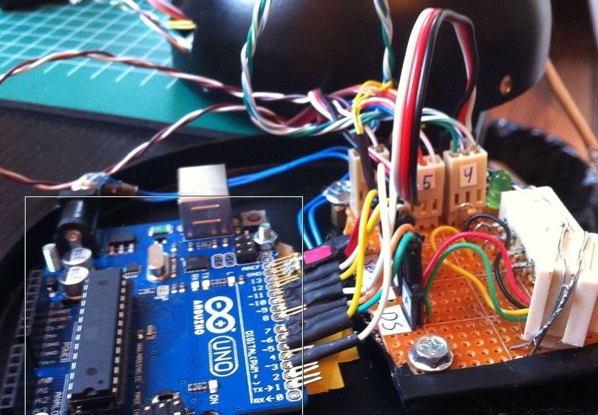
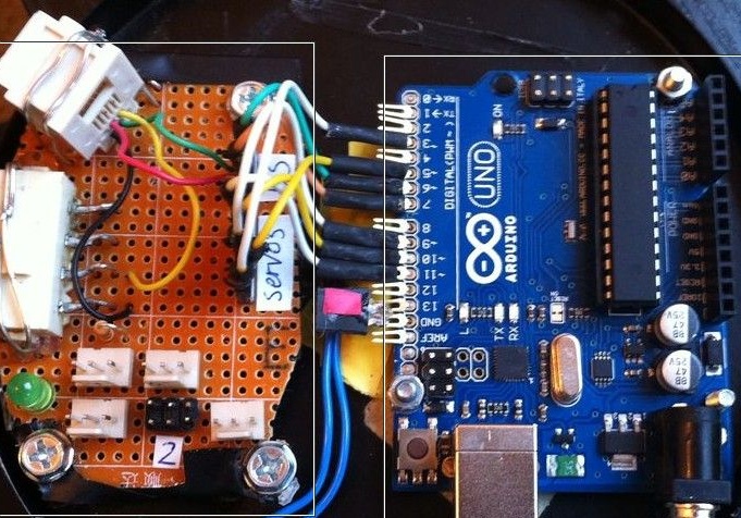
The outputs from the servomotors are connected to the PWM outputs on the Arduino. Such pins on the board are indicated by the “~” symbol. As for the ultrasonic distance sensor, it can be connected to pins 6 and 7. The LED is connected to ground and the 13th pin.
Now you can start programming. Before connecting via USB, you need to make sure that the power is completely turned off. When testing the program, the power of the robot must also be turned off. If this is not done, the controller will get 5V from USB and 12V from the power supply.
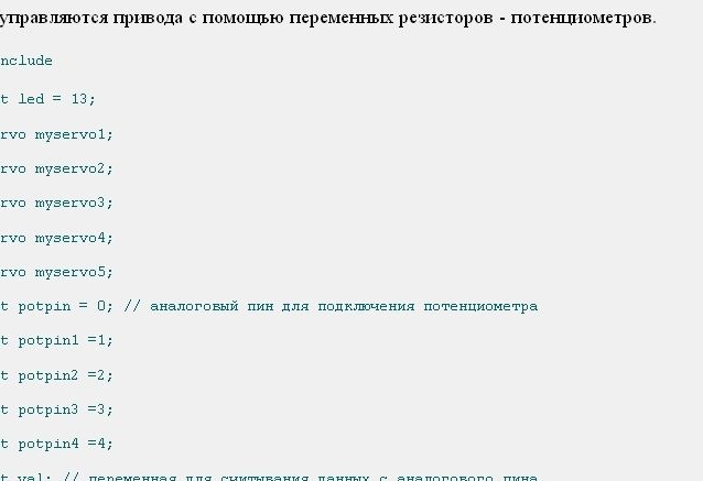
In the diagram you can see that potentiometers have been added to control the servomotors. They are not a necessary component of the robot, but without them the proposed code will not work. Potentiometers are connected to pins 0,1,2,3 and 4.
The circuit has a resistor R1, it can be replaced with a potentiometer of 100 kOhm. This will allow you to adjust the brightness manually. As for the R2 resistors, their nominal value is 118 Ohms.
Here is a list of the main nodes that were used:
- 7 LEDs;
- R2 - 118 ohm resistor;
- R1 - 100 kΩ resistor;
- switch;
- photoresistor;
- transistor bc547.
Step Four Programming and first launch of the robot
To control the robot, 5 potentiometers were used. It is quite possible to replace such a circuit with one potentiometer and two joysticks. How to connect a potentiometer was shown in the previous step. After installing the skchech robot can be tested.
The first tests of the robot showed that the installed futuba s3003 servomotors were weak for the robot. They can be used only for turning the arm or for gripping. Instead, the author installed mg995 engines. An ideal option would be mg946 engines.
That's all, the robot is ready. Now you can experience it, improve it and enjoy interesting homemade.