

Materials and tools for homemade:
- iron constructor (Mechanix kit);
- nuts and bolts;
- clothespin (or other holder for a pencil);
- two wheels (for supports);
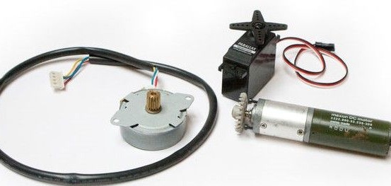
- type controller Arduino uno;
- power (source 5V 2A);
- bread board;
- USB cable;
- three servomotors;
- drill, screwdriver, key;
- required software (Arduino uno, Matlab).
The manufacturing process of the robot:
Step one. Development of mechanical elements of the robot
The mechanical part is assembled very simply, this is done from the constructor. A five-year-old child will also cope with this task.
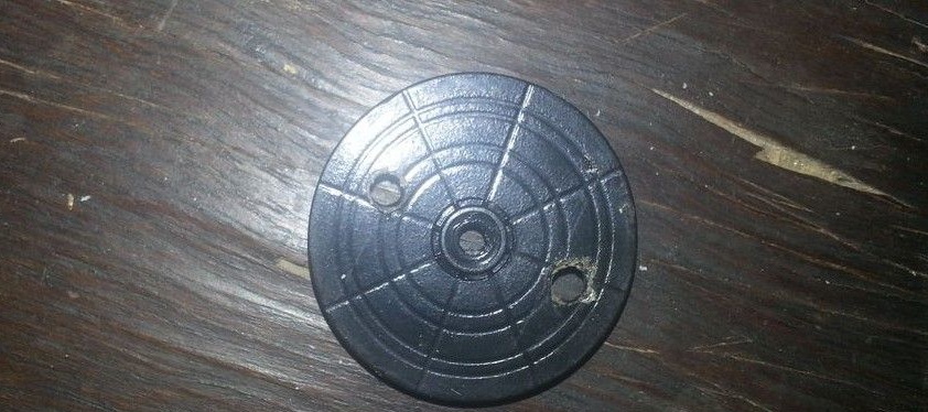
1. In the rockers from the servomotor, two holes must be drilled. The holes should be at a certain distance, which one is visible in the photo.
2. Now you need to make fasteners for the base with the drive. It is necessary to drill four holes for mounting the drive and then fix it with screws. The drive will be used as a fixed base for a robot arm.
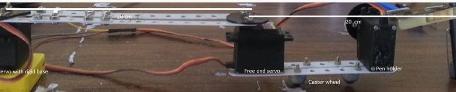
3. The aluminum links of the designer must be screwed to the rockers of the drives. It is desirable that the distance between the rockers is 20 cm.
4. One rocking chair needs to be attached to the motionless basis, and the second to the second engine. Before the rockers are locked, the servos must be calibrated. They need to be installed so that the shaft is at an angle of 90 degrees. The servomotor at the base should be parallel to the links, and the drive at the free end should be placed perpendicularly.
5. Next, the designer links are taken and attached in parallel to the free end and the servomotor.
6.To the bottom of the structure you need to attach the wheels, they are needed to balance the robot and its support.
7. The last motor should be connected to the end of the second link from the fifth paragraph.
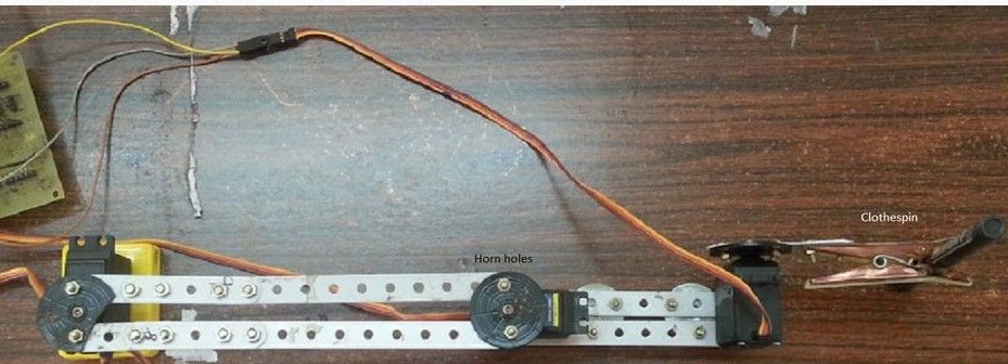
A clothespin is used to attach the pencil, you can also use any other suitable grip. It must be attached to the servomotor so that the distance between it and the working tool is about 20 cm.
During the assembly process, it is important to adhere to the indicated distances, as well as constantly calibrate the engines as they are assembled. Undoubtedly, the robot can be improved, but here it all depends on which nodes are available. If it turned out that there is no constructor, then you can use rulers, pieces of plastic and other suitable objects.
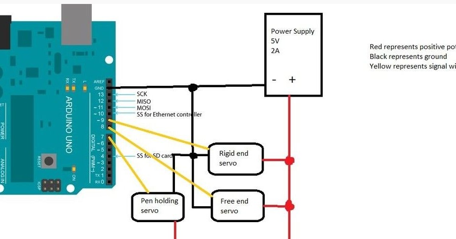
Step Two Robot circuit diagram
In the figure you can see how the Arduino controller is connected. To connect, you can use the breadboard or you can solder the shield.
Step Three Robot programming
Programming consists of several stages. First you need to take an image and find its borders. After that, you can start drawing, the drawing process consists of two stages.
First you need to find a pixel that matches the number 1, because the picture now looks like zeros and ones. In the process, a check is made to see if there are pixels with a unit nearby, after that the pen moves to the next unit, and deletes the previous one. The function is closed in a circle, which allows you to draw smooth lines.
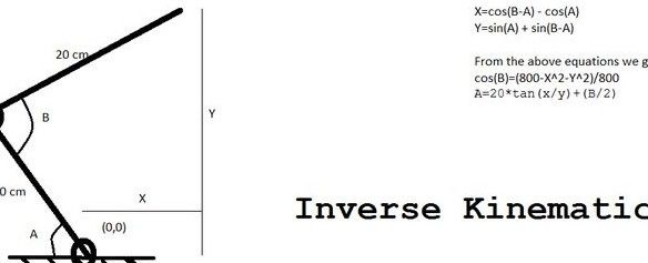
At the second stage, the inverse kinematics problem is solved. In this case, the coordinates of the pixels are taken into account and then, based on this data, the rotation angles of the servomotor are selected. What exactly happens when this happens can be seen in the figure.
Now you can proceed to configure Matlab and Arduino in order for the code to work. First you need to install the Arduino IO plugin in Matlab. Next, the file called arduino.m needs to be replaced with the one that is attached to the project with exactly that name.
The files finaldraw.m and draw.m need to be saved in a directory with Matlab. A file called adioes.ino is uploaded to the board.
In the next step, you need to check which port the Arduino board is connected to, open the finaldraw.m file, and replace the COM3 port with the correct one.
The extension of the drawing that you want to draw must be changed to a .png type. This is done very simply, you can use a graphical editor, for example, standard Paint. The file is saved in the Matlab directory.
Then you need to open the finaldraw.m file and replace emma.png with the name of the picture you want to draw.
As you can see in the picture, Emma Watson’s photo is used as a test.
That's all, the robot is ready to use, you can start testing. The Arduino board connects to a personal computer, and then the finaldraw command is written to the Matlab command line. The system is elementary tuned to the desired dimensions of the structure.