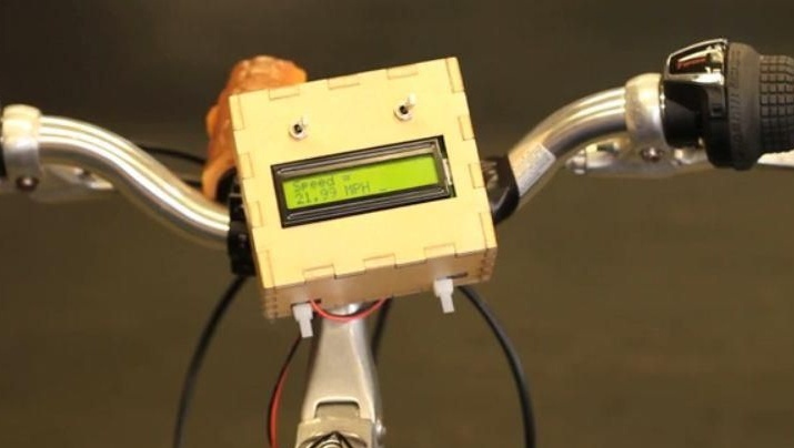
To calculate the speed of rotation of the wheel, a non-contact magnetic switch (reed switch) is used. When a permanent magnet passes by it, the signal goes to Arduino, here the speed is calculated in miles or kilometers per hour, as a result the numbers appear on the display, they show the speed. You can install such a device on any wheel, and not even a bicycle one. The main thing is to correctly indicate the radius of the wheel, because it is on the basis of these data that the speed is calculated.
Materials and tools for manufacturing:
- microcontroller Arduino;
- magnetic switch (reed switch);
- resistor (10 kΩ, 1/4 watts);
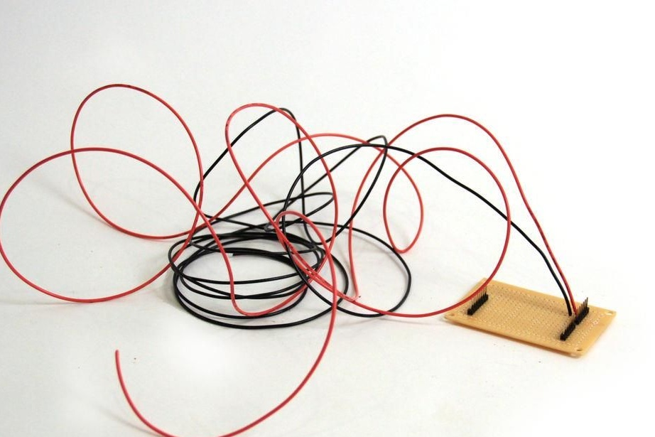
- the wire;
- 9V battery;
- LCD display;
- breadboard for desoldering;
- two switches.
Still need plywood, screws, a certain amount of tool. Well, of course, the Arduino IDE software.
Build process:
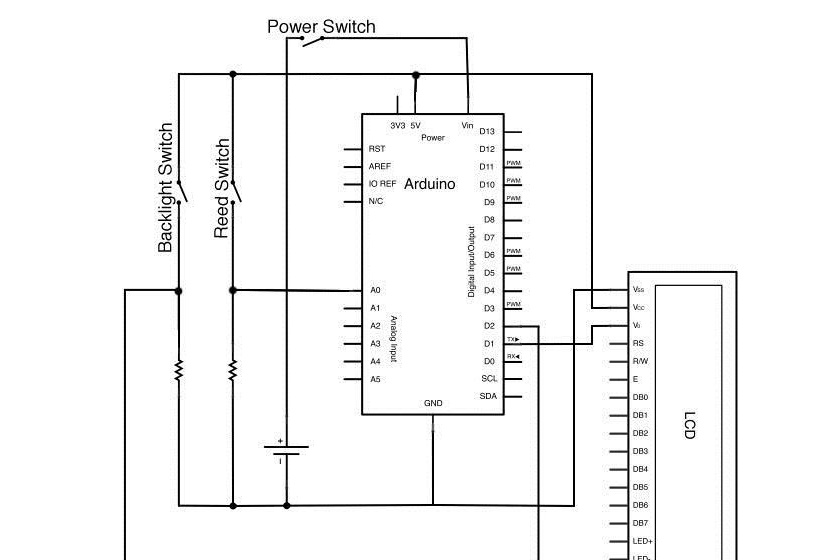
Step one. Speedometer circuitry
In total, the circuit uses three switches. One switch controls 9V power. The second switch is responsible for the operation of the LCD screen, with it you can turn it on or off. And finally, the magnetic switch of the reed switch, it closes the circuit if the wheel makes one full revolution.
The project uses a Parallax LCD monitor; it is connected to the board using three pins. 5V is applied to one pin, the second is connected to ground, and the third output is digital, it is marked with the number 1.
10 kΩ resistors play a protective role in the system so that no overload occurs. You can not connect the ground and plus 5V to the Arduino directly.
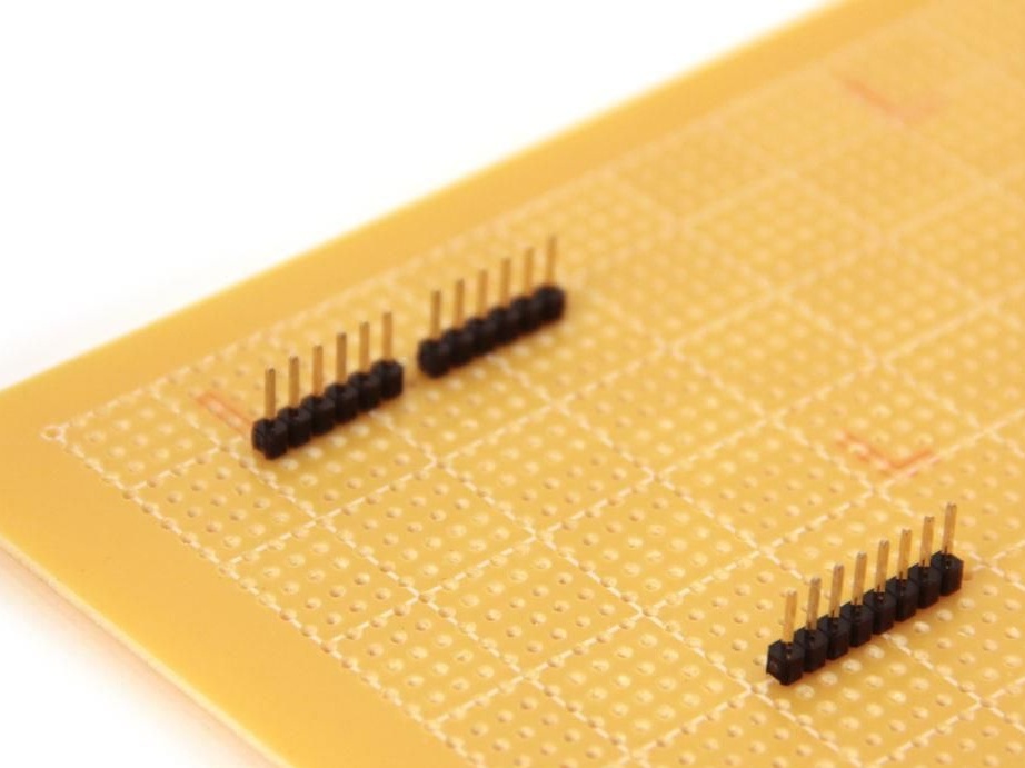
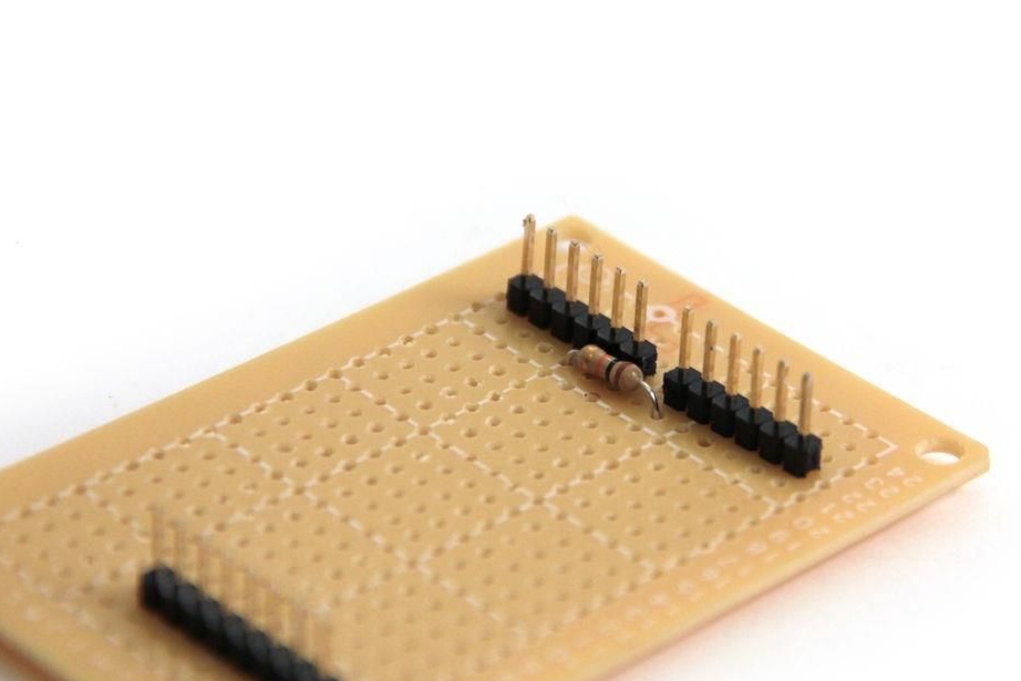
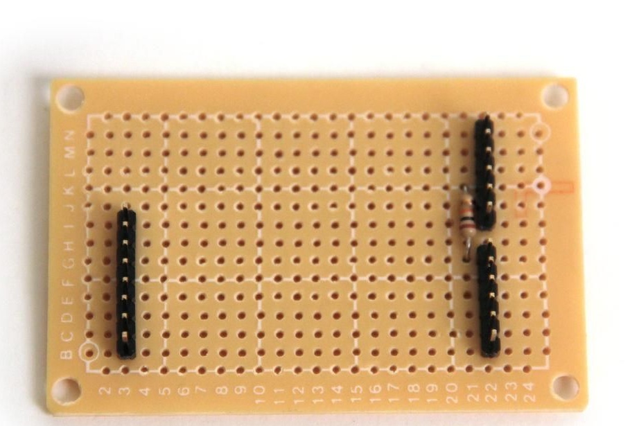
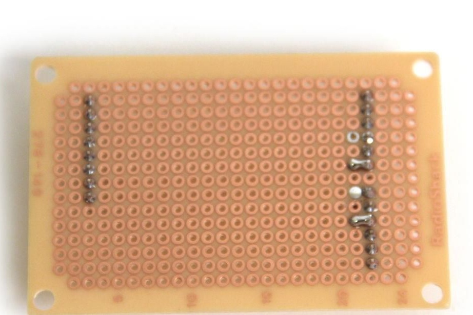
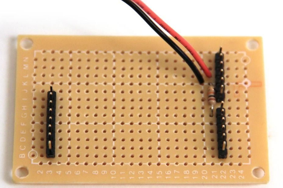
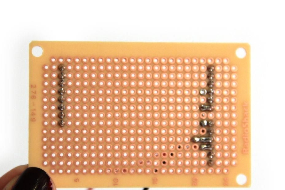
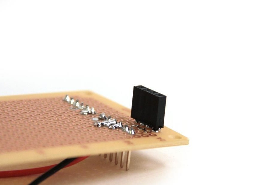
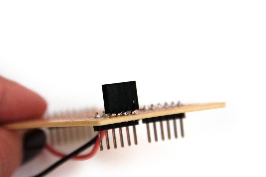
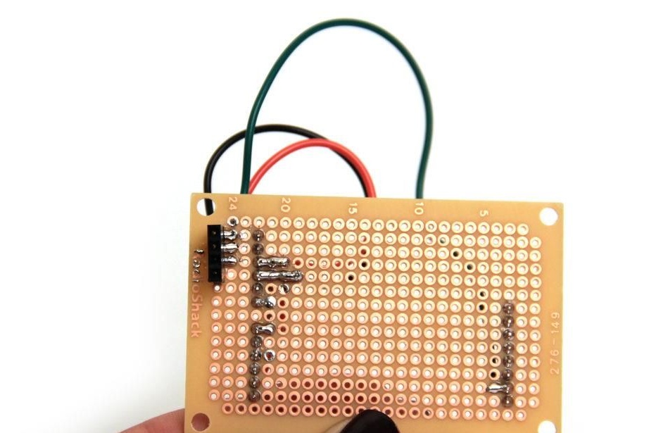
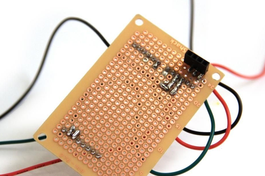
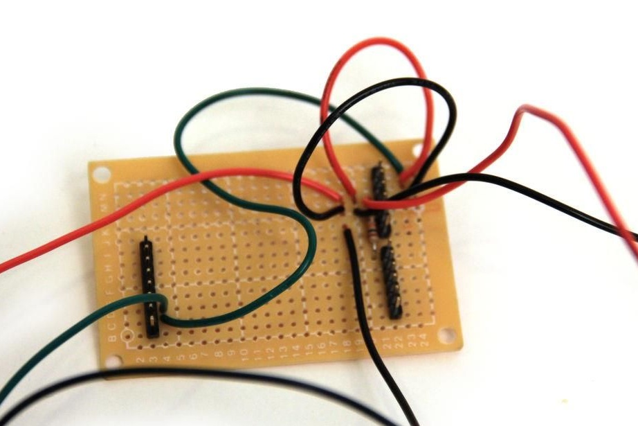
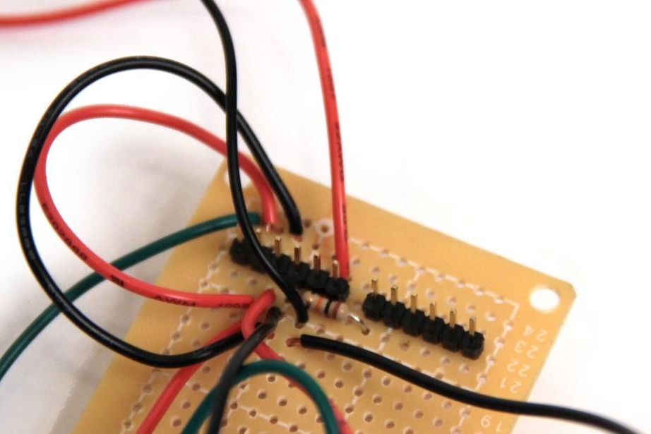
Step Two Solder the shield for the speedometer
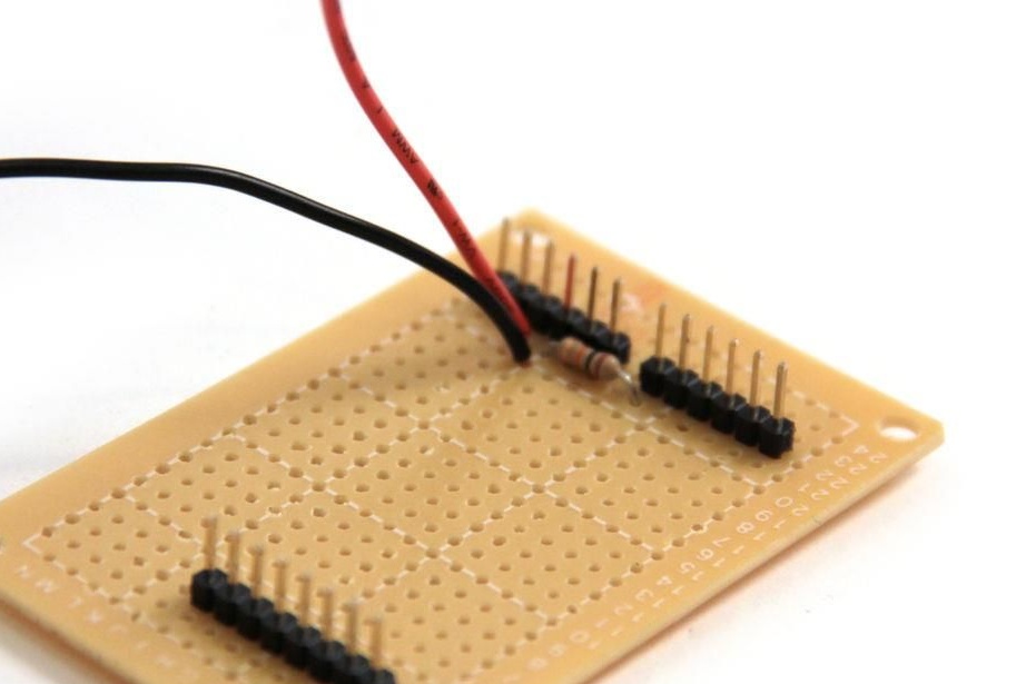
Three rows of connectors must be installed on the breadboard; they must sit on the board in the manner shown in the picture.
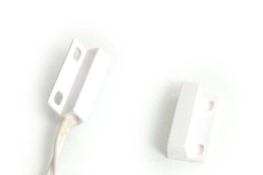
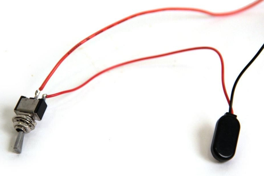
Step Three Installation and connection of a reed switch
Reed switch consists of two elements, a switch and a permanent magnet. Two wires come out from the reed switch, when a magnetic field acts on it, a small magnetic element inside the switch moves and closes the circuit.
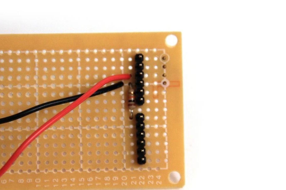
Between pin A0 and ground, a 1 kOhm resistor must be installed on the breadboard. The ends of the wire are connected to the outputs A0 and 5V.
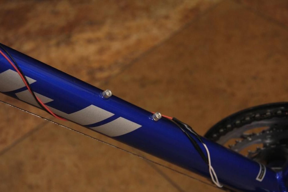
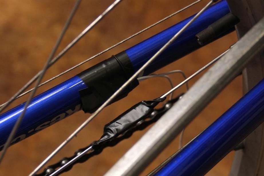
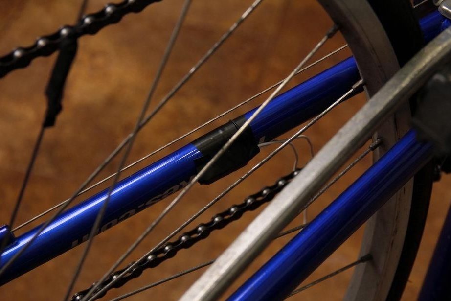
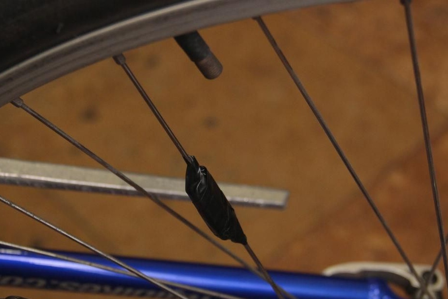
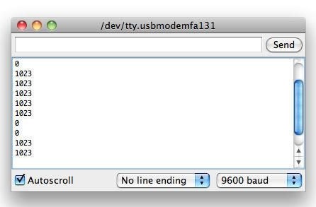
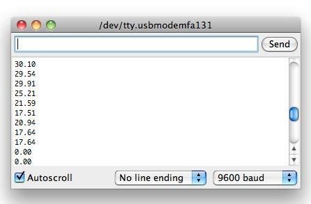
As for the mechanical part, the reed switch is installed as follows.A permanent magnet is attached to the wheel spoke. The reed switch itself is mounted on a wheel fork opposite the magnet. There should be a small distance between the reed switch and the magnet, otherwise it will not work. Next, the wires are connected to the outputs of the soldered board, and a performance check is performed. When the magnet passes near the reed switch, Arduino should output ~ 1023. If the system does not work, 0 will be displayed.
In the Arduino IDE shell, you need to open the serial monitor (Tools - Serial Monitor) and run the test. If there is no signal during wheel rotation, you need to replace the magnet with a more powerful one or reduce the distance between the sensor and the magnet.
If there is a signal, you can download the code to check. When the wheel does not spin, the value 0.00 should be displayed. When the wheel rotates, the speed should be displayed in miles per hour.
Step Four Check and install LCD
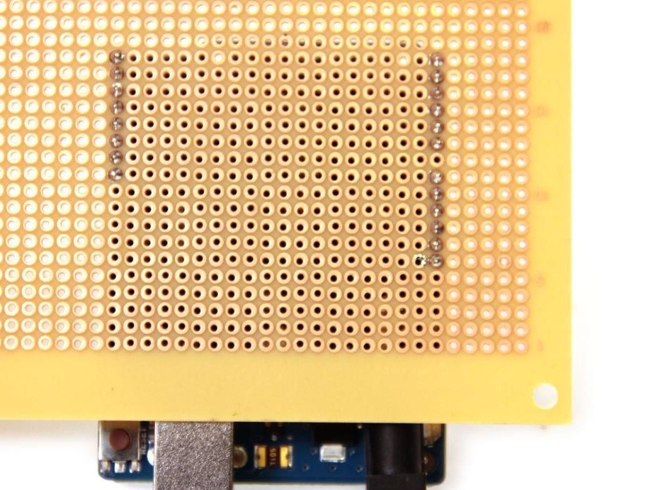
To install the display, you need to take an additional shield. The rail needs to be soldered to the “mother” contacts on the protoshield output. Three contacts are used to connect the screen, it must be tightly mounted on the rails.
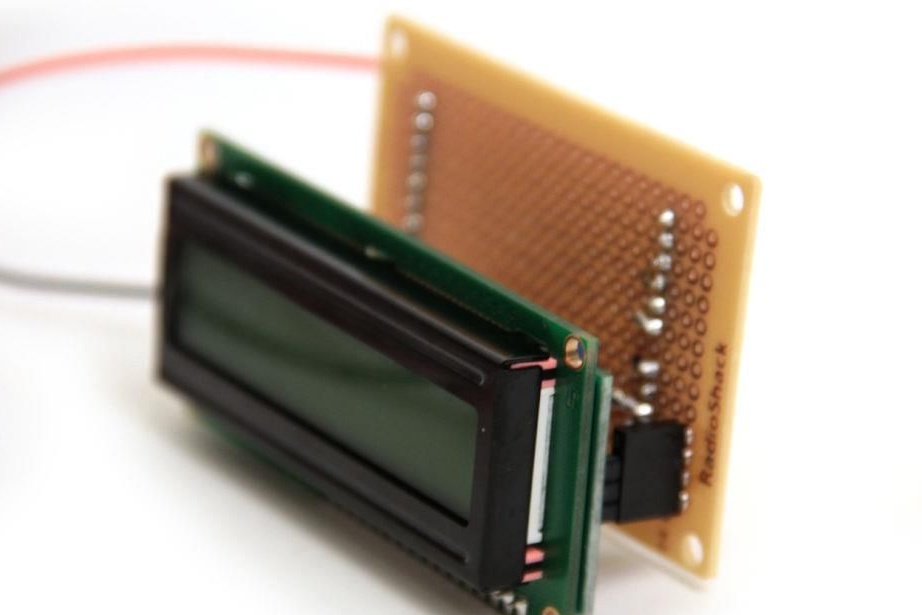
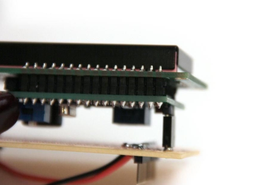
On the back of the LCD screen, you can find two switches, as well as a potentiometer. The switches must be moved to the position shown in the picture. A potentiometer is used to manually adjust the screen contrast.
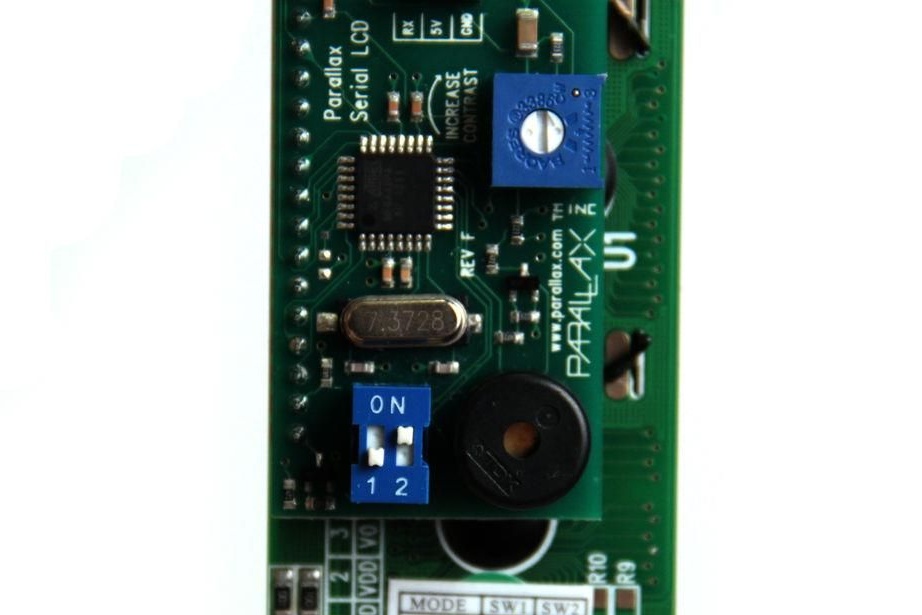
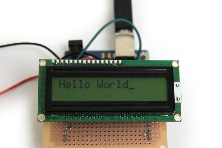
After installation, the display can be checked. If everything is done correctly, then the message “Hello World” will appear on the screen. It is possible that the first time it does not work out and you have to re-reload the sketch.
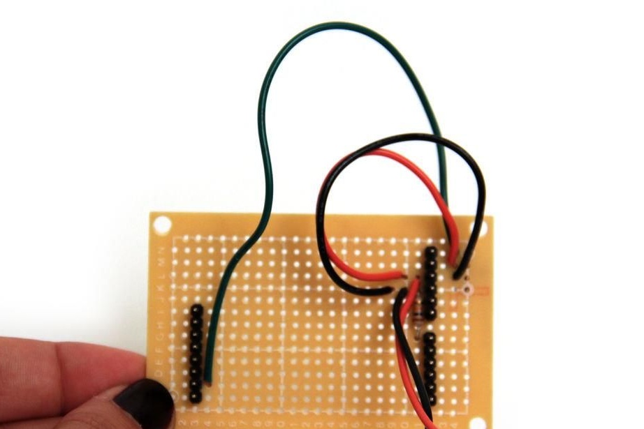
Step Five Speedometer backlight
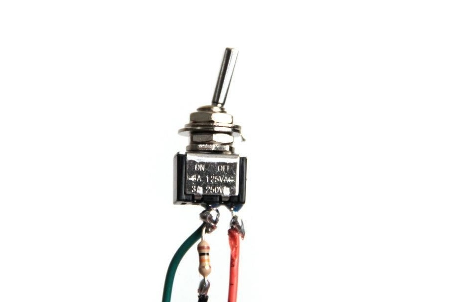
Now you need to connect the backlight toggle switch. This is done as indicated in the pictures. You must remember to connect the 10 kΩ resistor to the green and black wires. Further, these wires are connected to one contact of the switch, and the red wire is connected to the second.
The red wire is power, it connects to the Arduino 5V. The green wire connects to D2 and the other side of the resistor to ground.
Step Six Speedometer Power
Use a switch in the power circuit. The black contact from the battery is connected to the ground, and the positive through the switch is connected to the Vin output.
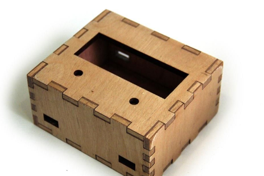
Seventh step. The final stage of assembly and installation of the speedometer
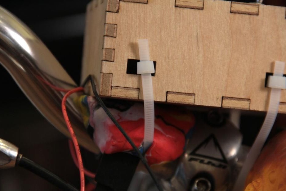
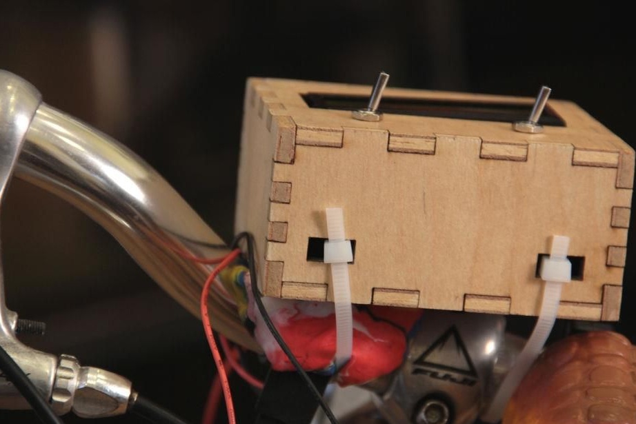
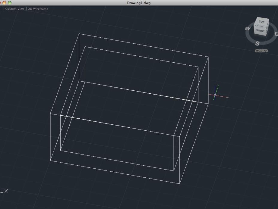
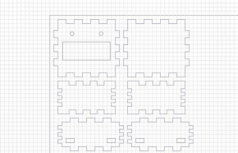
A box is used as the body, which is cut out of plywood. The body elements are cut using laser cutting according to the designed patterns. Further, all the elements are interconnected with glue. In conclusion, plywood is painted or varnished to protect and give appearance.
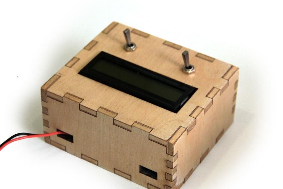
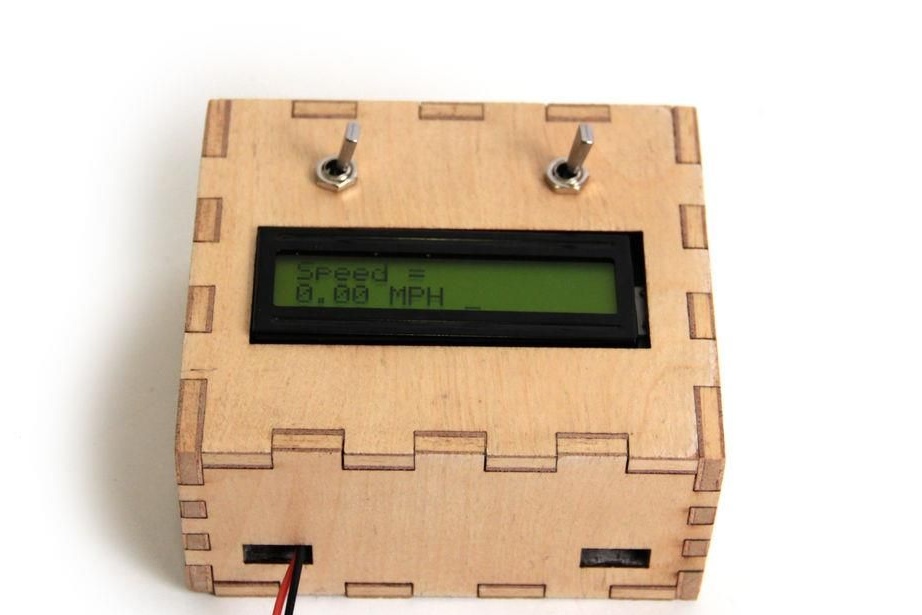
The speedometer is mounted on the steering wheel with nylon ties. You can use other elements. That's all, now the speedometer is ready and you can watch how much your iron horse squeezes.