
This article is based on the ideas of the last century, the author tried to repeat it using neodymium magnets. The point is that you do not need one powerful generator of electricity and, accordingly, the same drive for it. You can use one drive and several less powerful generators operating on the same load, connected with themselves in this particular case, through a magnetic gear.
I have seen a magnetic gearbox based on this principle. There were a couple of patents on the Internet.
What you need for a prototype:
- engines of CD / DVD drives 5 pcs.
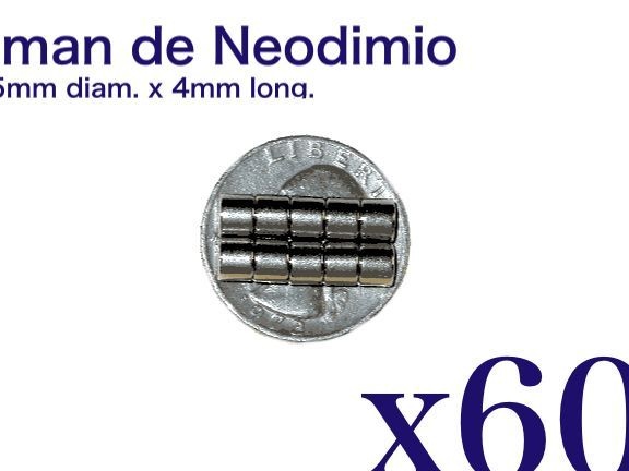
- Neodymium magnets 5 mm in diameter and 4 mm in height 60 pieces
-Bread board
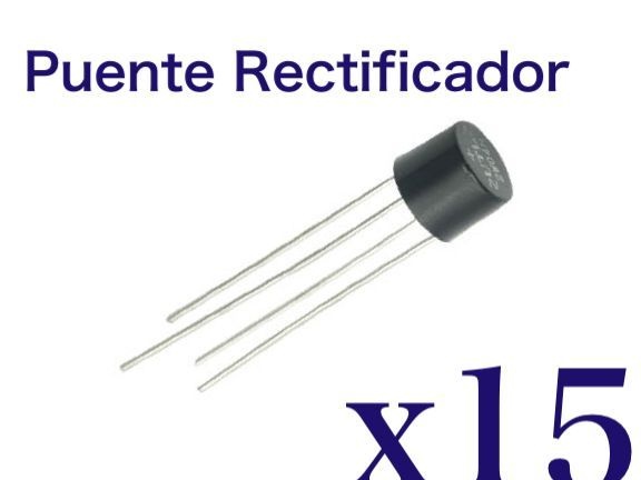
- diode bridges 200v 2A 15 pcs.
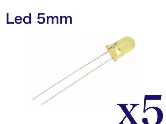
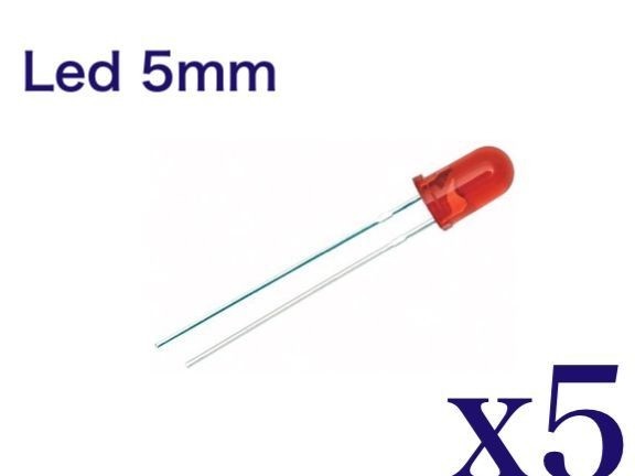
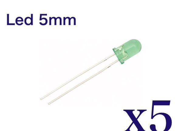
- LEDs red, yellow, green 5mm for 15 pcs. every
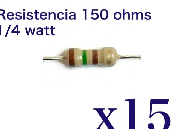
- resistors 150 Ohms 0.125 W 15 pcs.
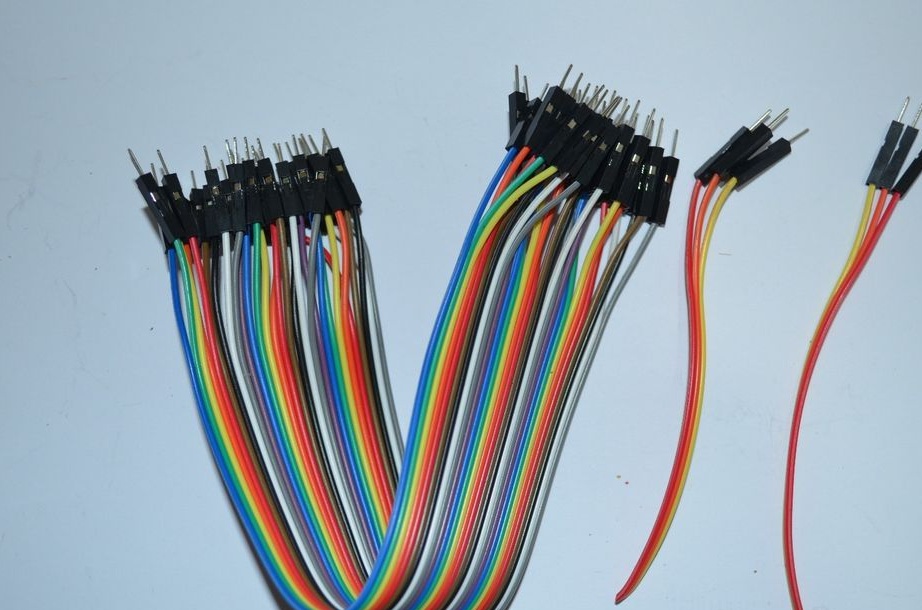
wire
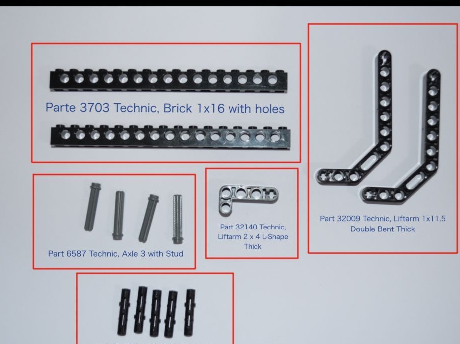
Lego:
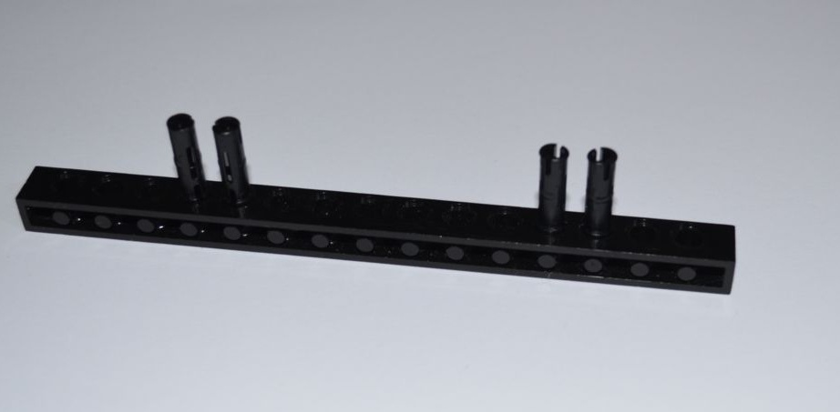
• Brick 1x16 (LEGO No. 3703) - (10 pcs)
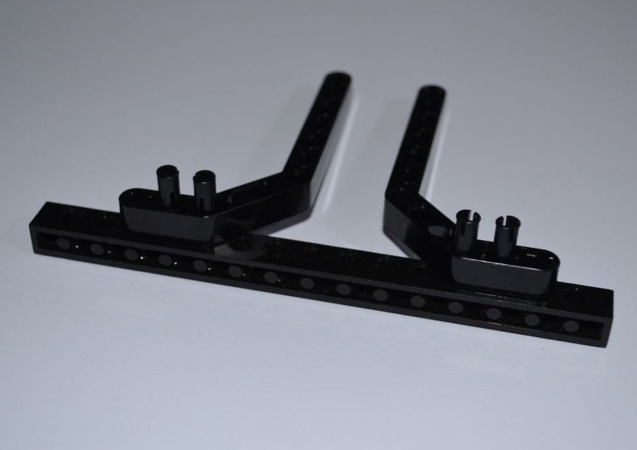
• Liftarm 1x11.5 (LEGo No. 32009) - (10 pcs)
• Liftarm 2x4 L (LEGO No. 32140) - (15 pcs)
• Axle 3 with Stud (LEGO No. 6587) - (20 pcs)
• Pin Long with Friction (LEGO No. 6558) - (25 pcs)
Glue, heat shrink with a diameter of 1.5 mm, fluorescent paint orange and green

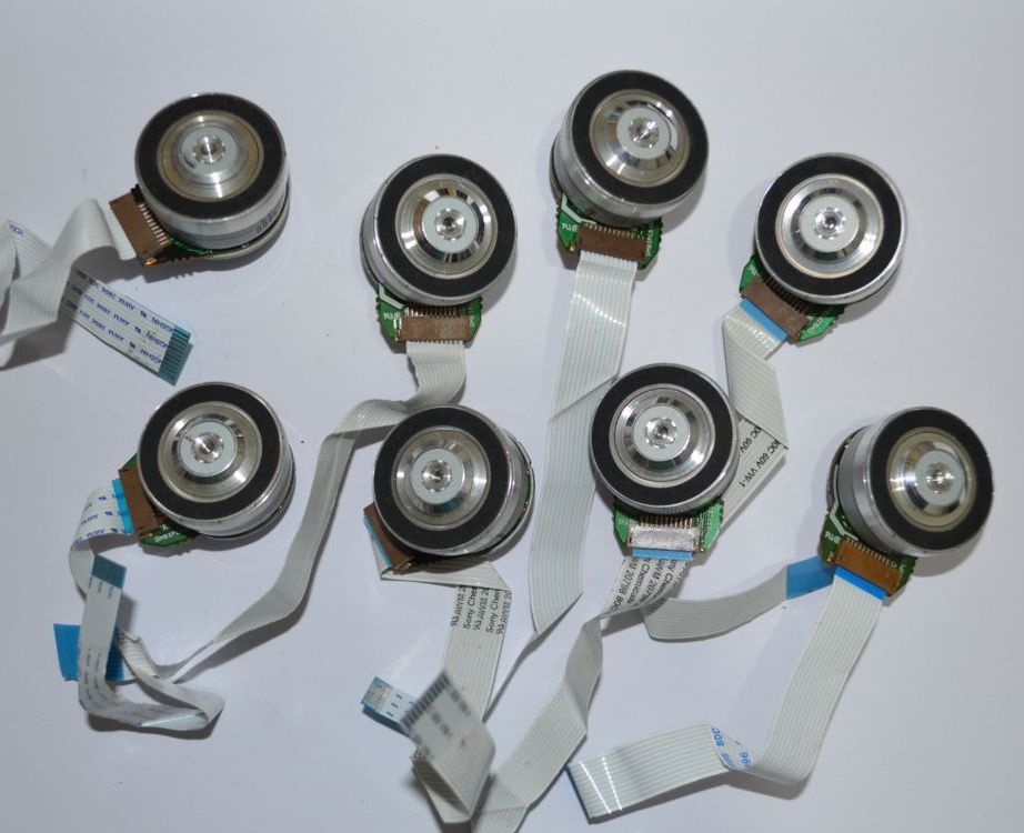
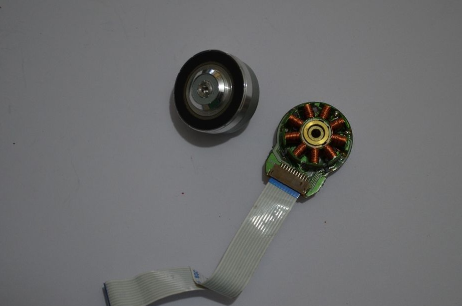
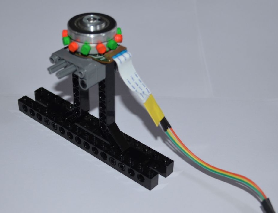
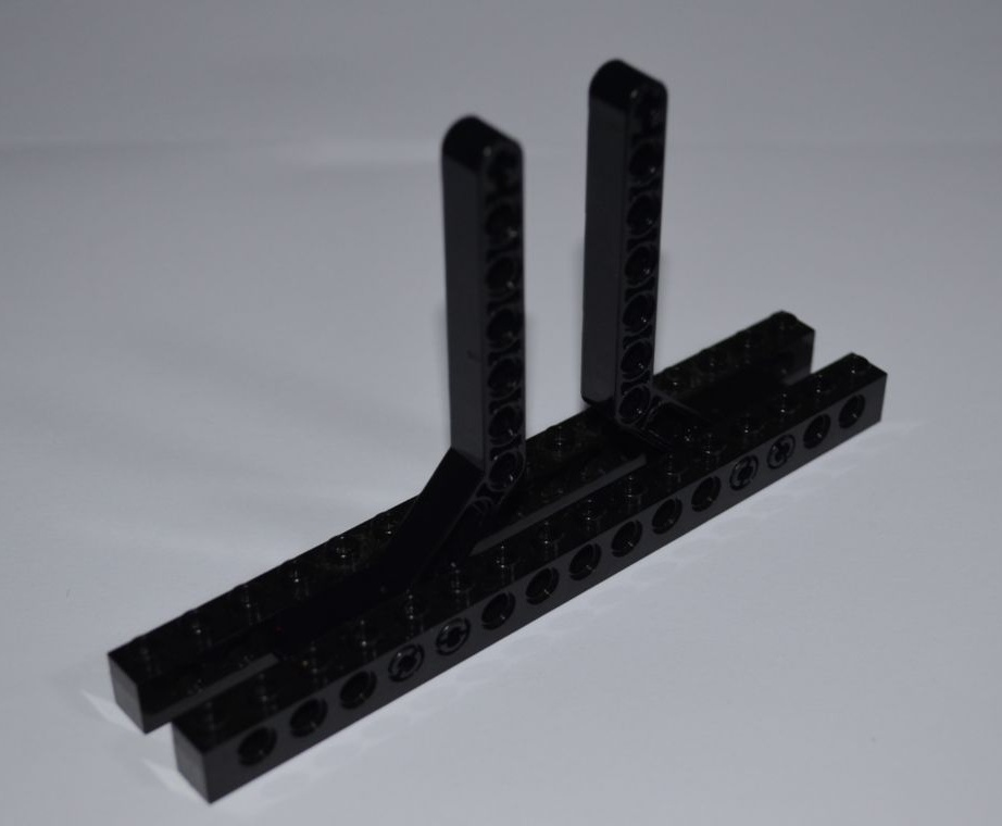
MOUNTING ENGINES
The motors that are used in this design are brushless (valve), for more details about them can be read
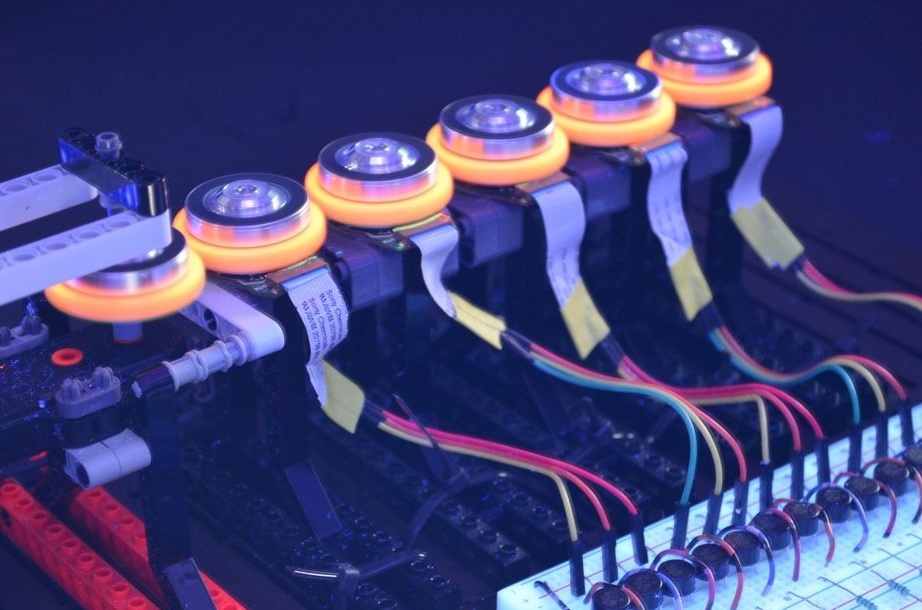
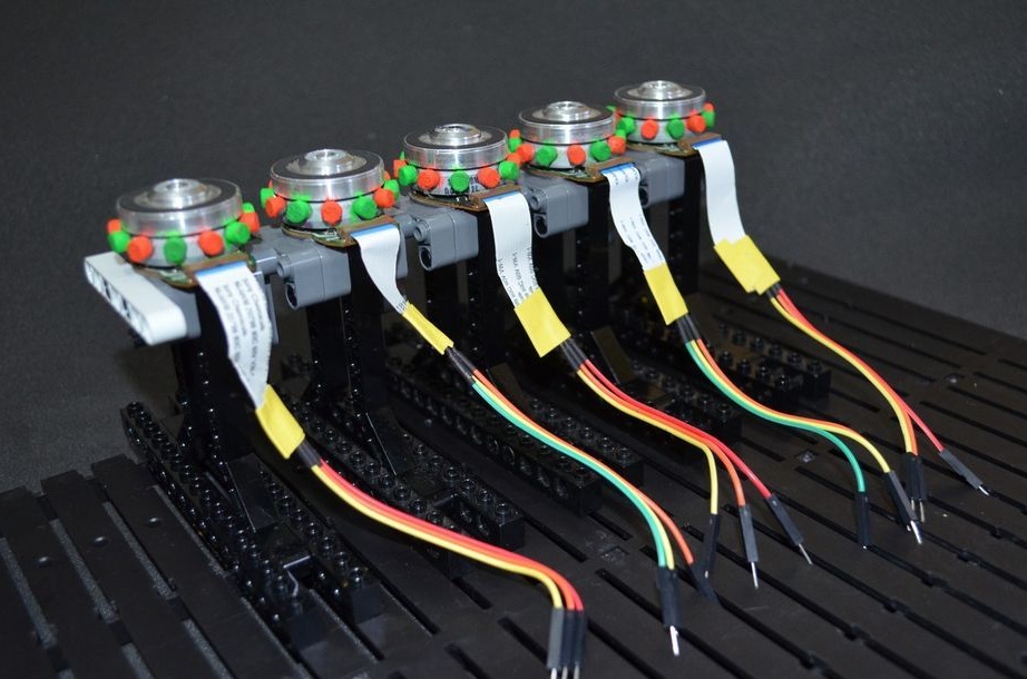
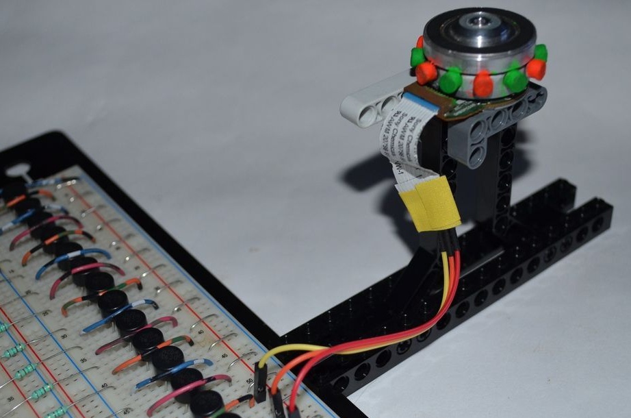
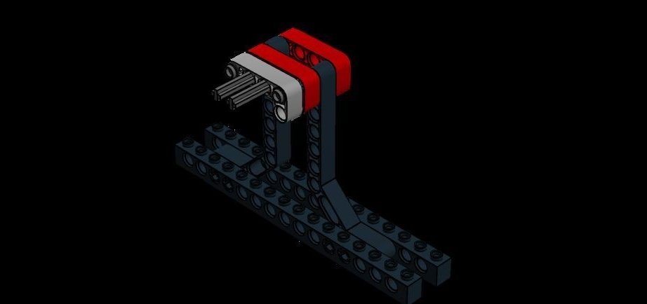
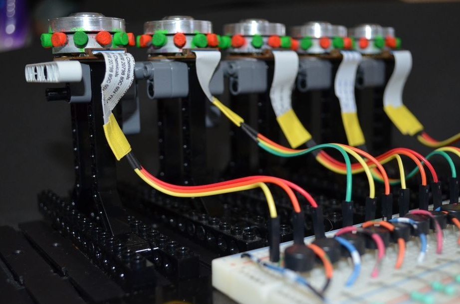
Installation of engines is carried out on parts from LEGO as shown in the photo,
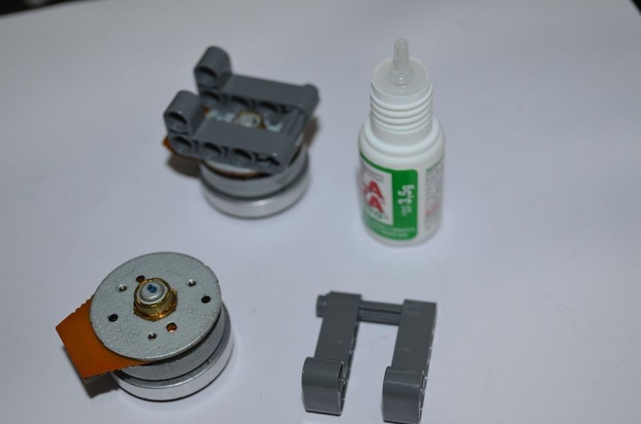
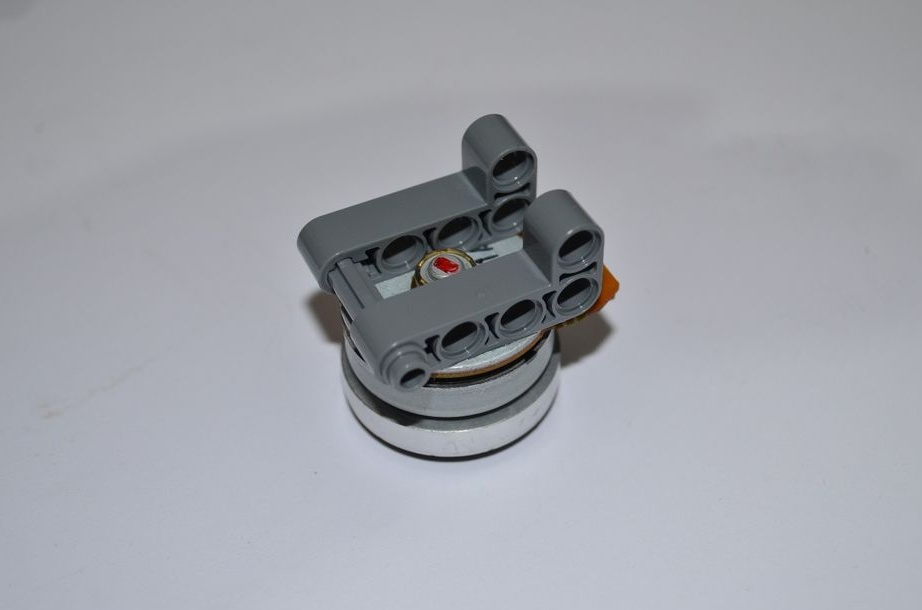
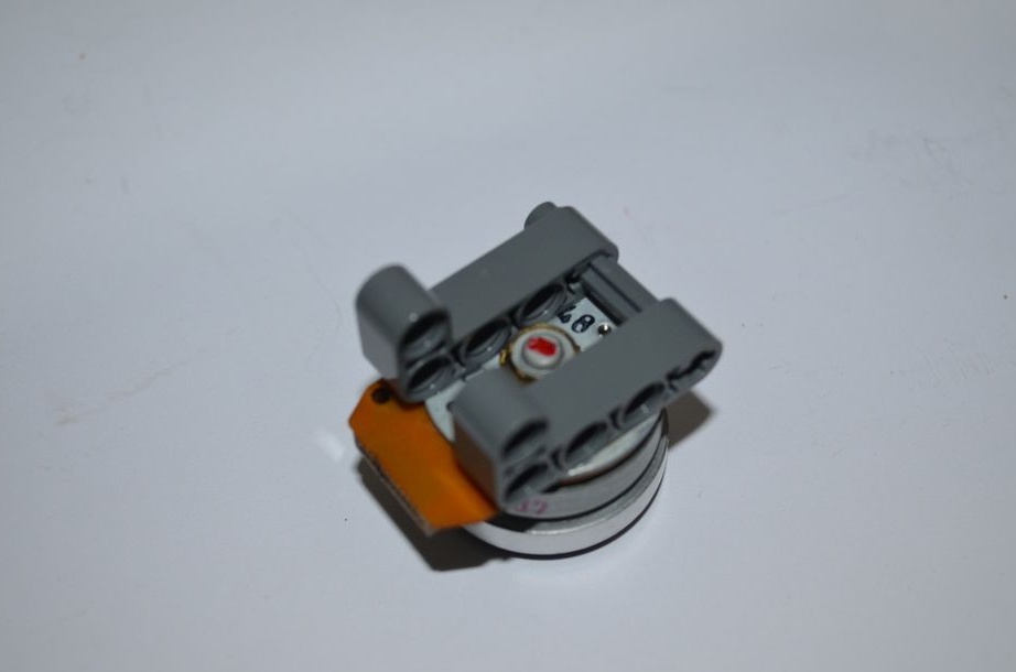
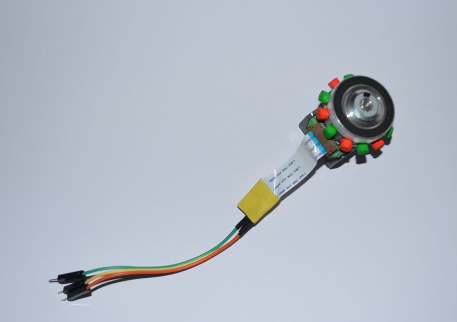
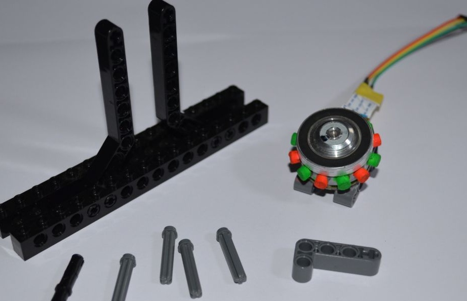
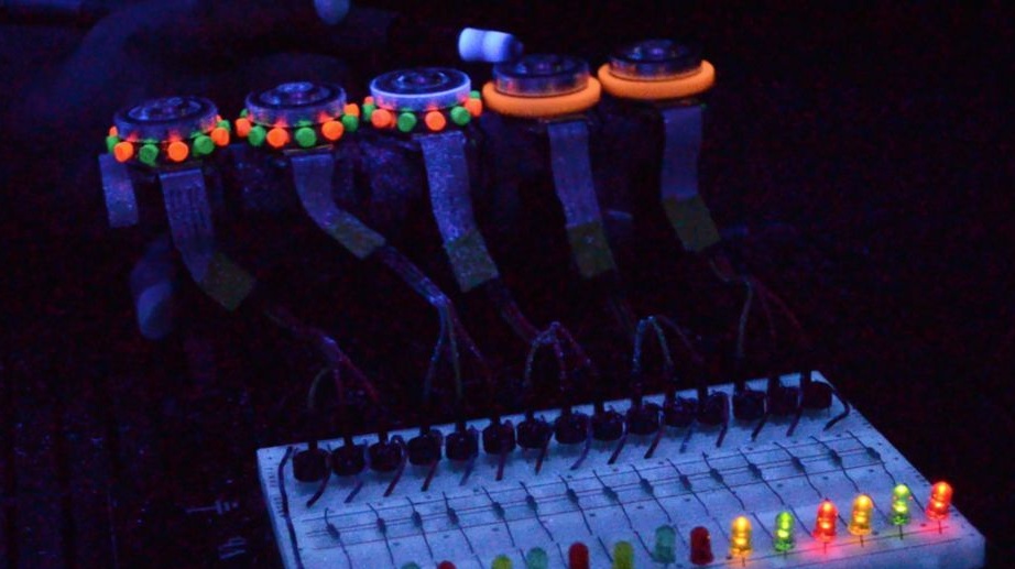
Using cyanoacrylic glue. Do not want LEGO- come up with your own bracket. Then place magnets on the motor so that their poles alternate S-N-S-N-S. The author does not write about this, but it is probably better to outline the arrangement of magnets in some program in advance.
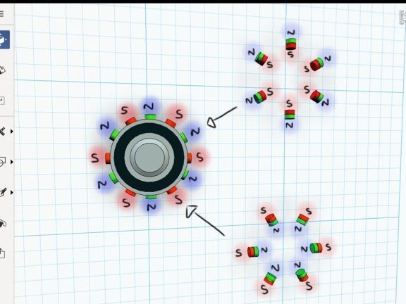
But keep in mind that magnets are powerful and very fragile, if they are attracted from a long distance, they will simply crack. It happened to me. From about 20 cm the magnets collapsed and one of them simply crumbled. Due to the high speeds of rotation, the magnets must be glued to the motors, otherwise they will simply fly around the room. After the sticker, paint each magnet in different colors so that the work can be better seen.
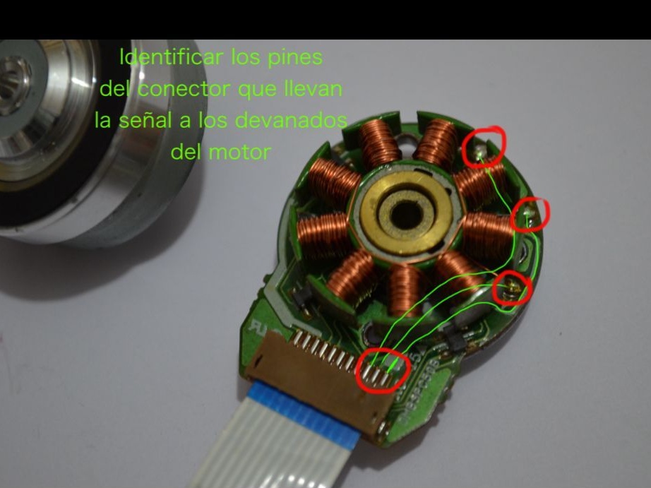
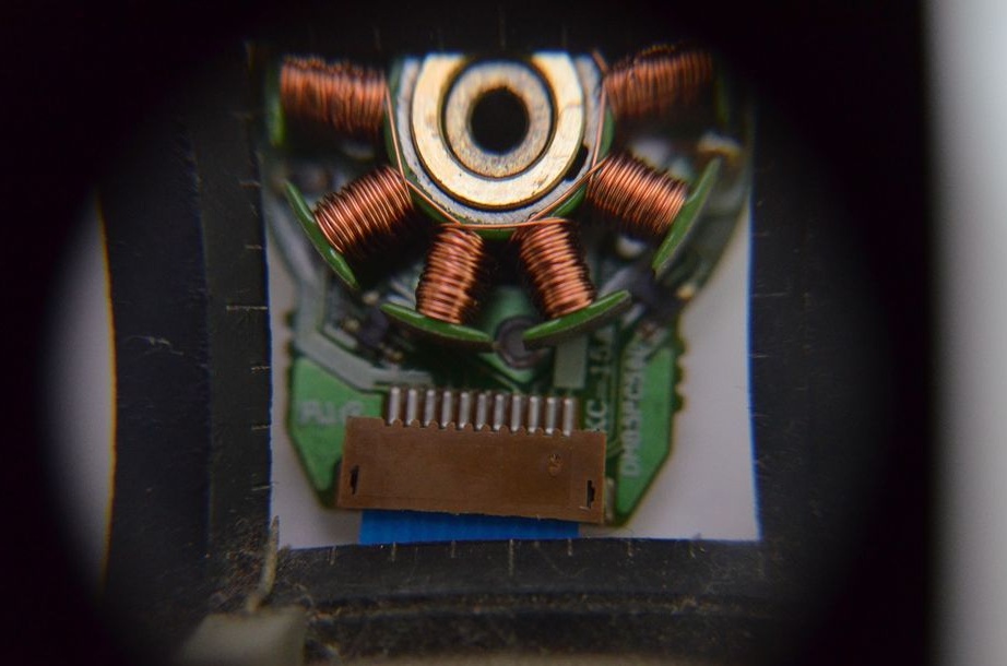
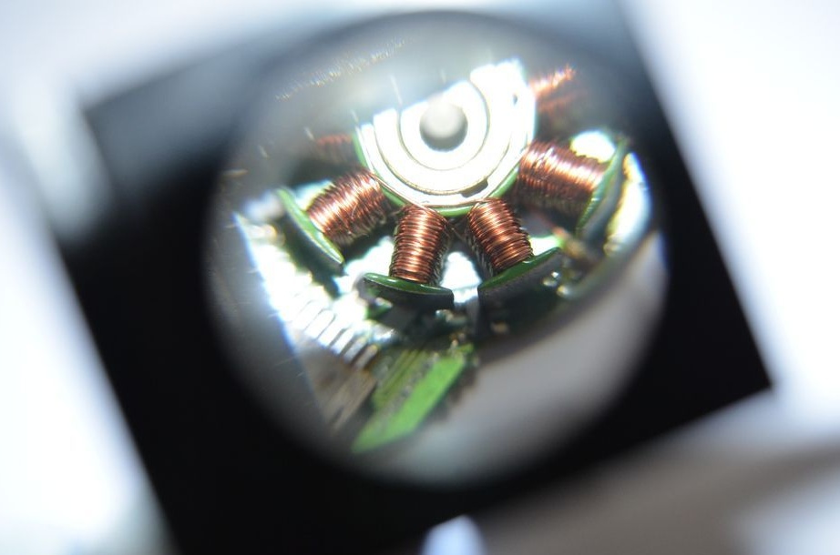
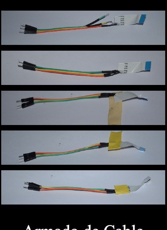
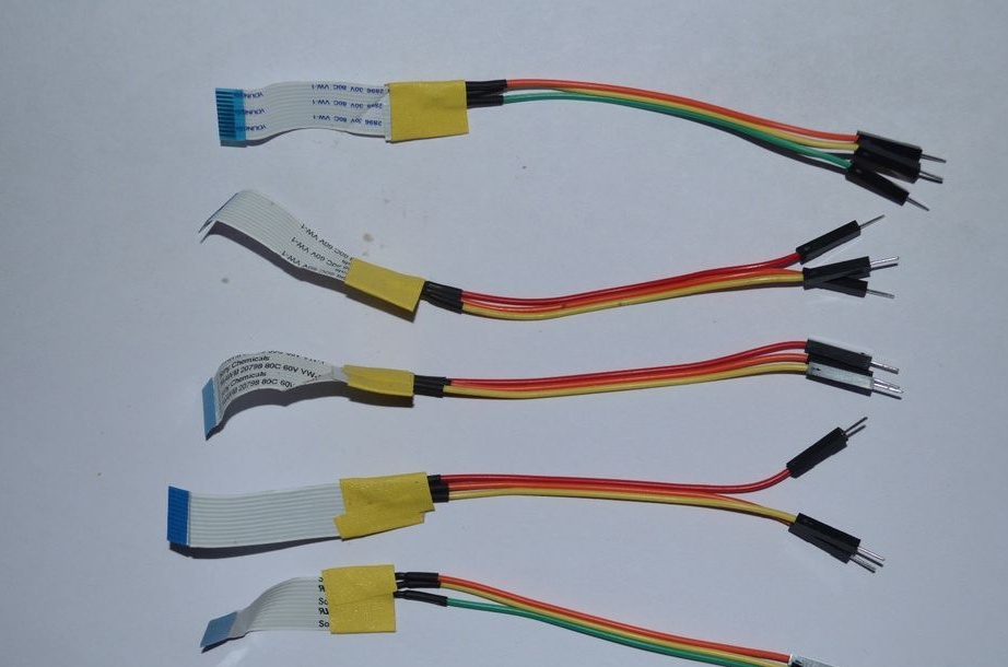
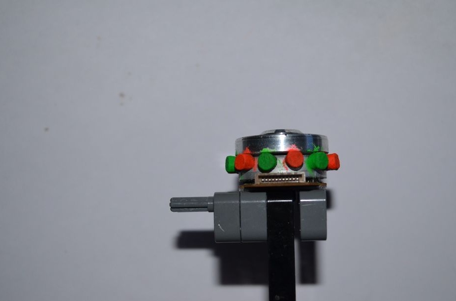
Connection of engines.
Each of the motors has several coils connected together in 3 phases. It is necessary to determine to which conclusions of the loop these three phases are connected. This can be done by following the tracks on the circuit board with a magnifier.
Gently solder the wires to these terminals.

We assemble an electric circuit.
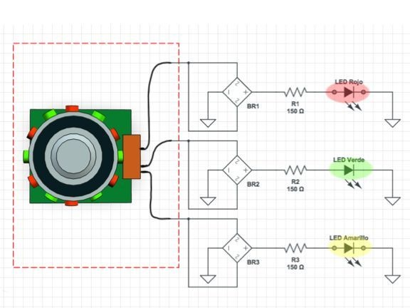
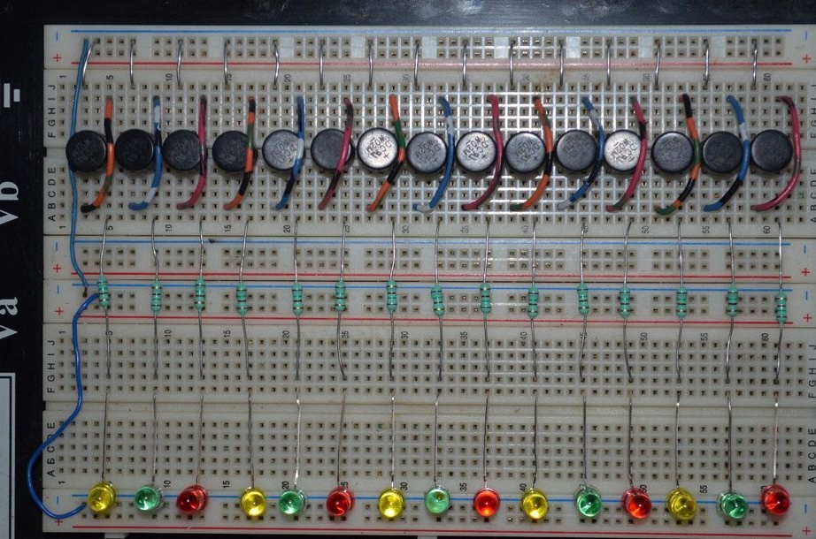
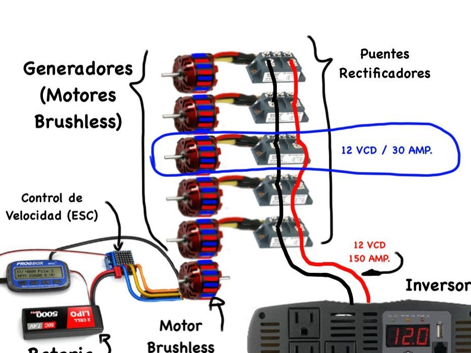
In valve motors, which are used as generators, in this design, the output will be an alternating three-phase voltage. To obtain a constant voltage, full diode bridges are used.Half-bridges can also be used, but this will reduce the maximum possible load current. In the diagram, each phase is connected to the LED, this is done for clarity. In practice, all phases after the rectifiers will be connected together.
We assemble the entire structure
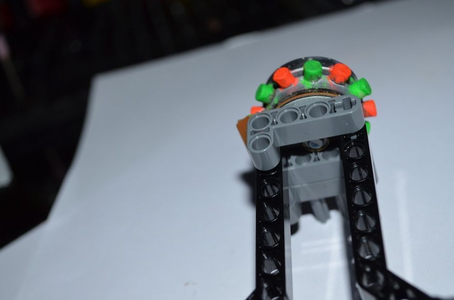
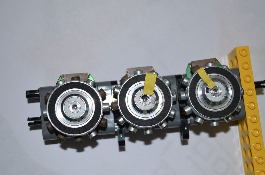
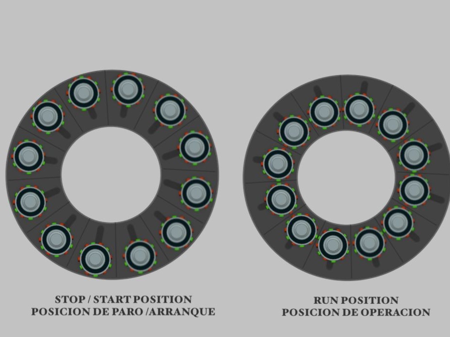
Place the engines next to each other as shown in the photo. The closer you place the engines to each other, the higher speeds you can achieve without losing synchronization between the engines.
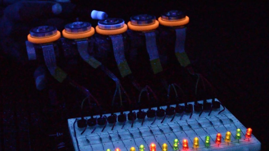
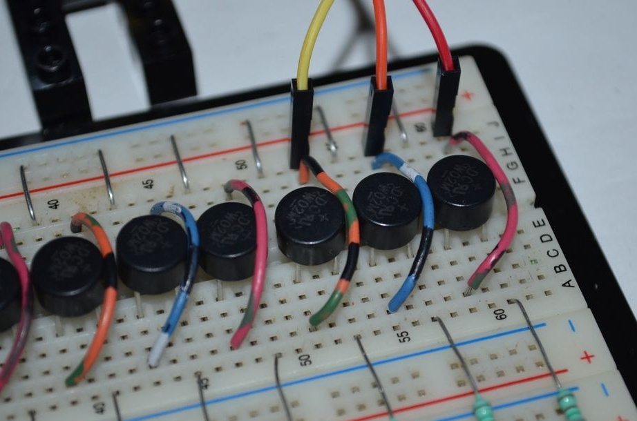
Connect all motor leads to diode bridges. IMPORTANT: motors need to be firmly fixed to the base, they will rotate at high speeds and strong vibration will appear due to unbalanced magnets weights.
After the assembly, several tests were carried out, here is what turned out during the experiments:
The faster the motors rotate, the greater the output voltage (Faraday Law)
The faster the engines rotate, the higher the probability of separation of the magnets: wink :: wink:
If you increase the distance between the engines, they will be easier to crank, but at high speeds, synchronization is lost. If the gap is reduced, then in order to crank them you need more effort, but then the synchronization is not broken.
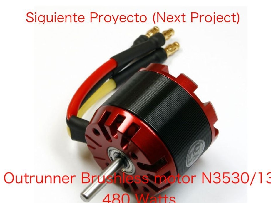
Recommendations for the next step:
Use OUTRUNNER brushless motors less than 1000KV (KV = RPM / Volt).
The photo above shows an example of controlling the speed control and output power. Pay attention to the heating of engines per minute to ensure optimal operation and, if necessary, provide cooling. (OUTRUNNER engines from boats come with water cooling)
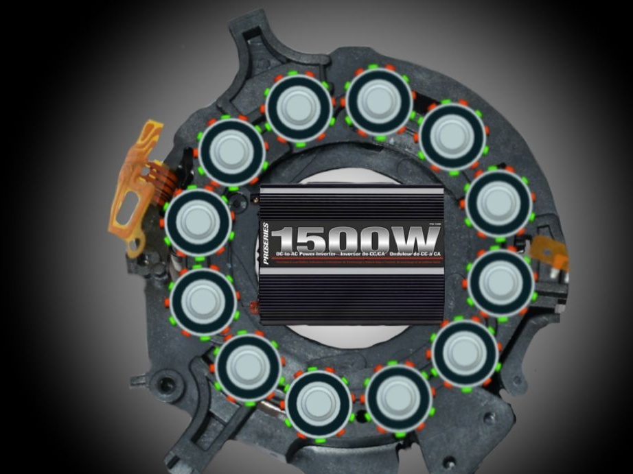
The author uses engines from CD / DVD drives 12v 1A, which gives 12W of power. If you use engines from aircraft models, you can get impressive results, as there are small engines of several hundred watts. If you tie them together you can get a power of 1500 watts.

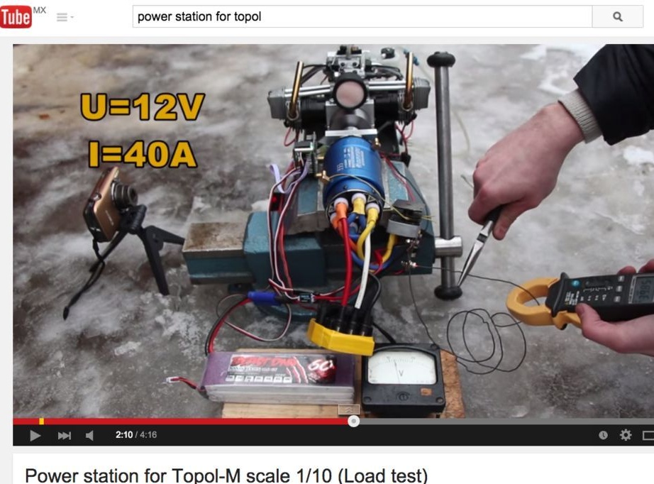
In the photo below, the prototype drive Topol M
You can also change the configuration of the generators to adapt it to the load.