This device allows you to connect a dynamic microphone, electric guitar and other signal sources with high output impedance to the computer sound card. The device does not introduce frequency distortions in the audio frequency range, as well as distortions associated with the nonlinearity of the amplifier device, since it is built according to the source repeater circuit.
In other words, if you are at least a little worried about the quality of the recorded sound, you have a good sound card and an expensive microphone, then this device is what you need.
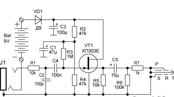
A bit about the scheme. The device starts to work if a mono-jack is inserted into the J1 connector, or, if scientifically, a plug with a diameter of 6.35 mm (1/4 inch). At the same time, through the jack, the negative contact of the battery closes to negative power and the device starts to work. Also, the second contact of this plug input signal is applied to the resistor R1, providing a high input resistance of the device. Capacitor C2 makes frequency adjustments by trimming frequencies above the audio range. R2-R4 resistors provide the necessary bias on the gate of the field effect transistor.
In this design, a KP303 field effect transistor with an index of E is used. When using a transistor with a different index, it may be necessary to reduce the values of the resistors R3 and R4. The resistor R5 is the load of the amplifier stage, the sound signal is removed from it by the capacitor C5 and is fed through the resistor R7 to the input of the computer's sound card.
The diode VD1 in the circuit performs a protection function
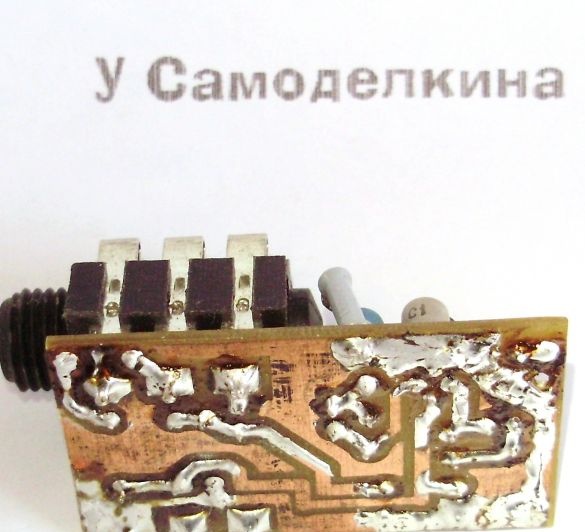
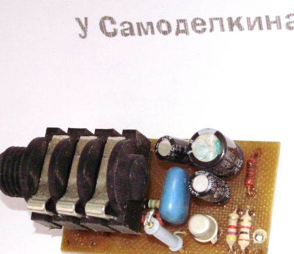
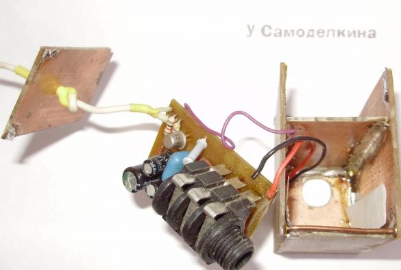
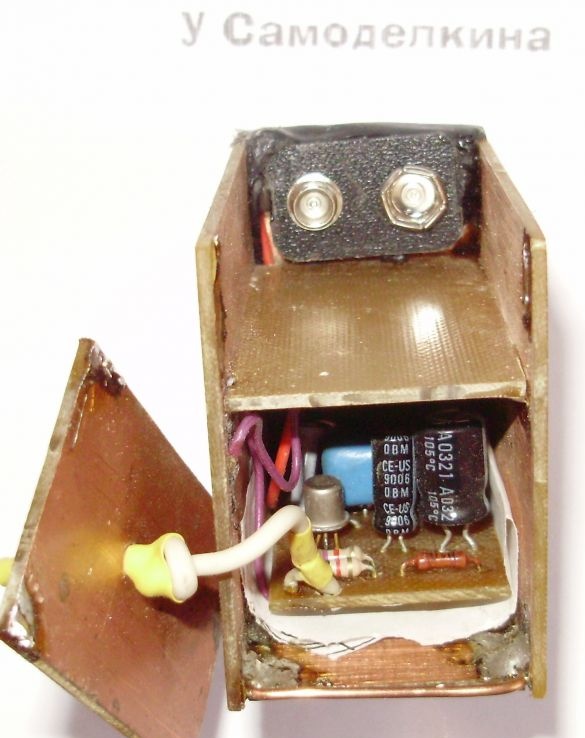
The device is assembled on a board from a single-layer foiled textolite with dimensions of 47x26 mm. The board trace in the Dip Trace program will be given below.But you can do without making the board, and assemble everything on a universal circuit board (this is the one with a bunch of holes) of the same size.
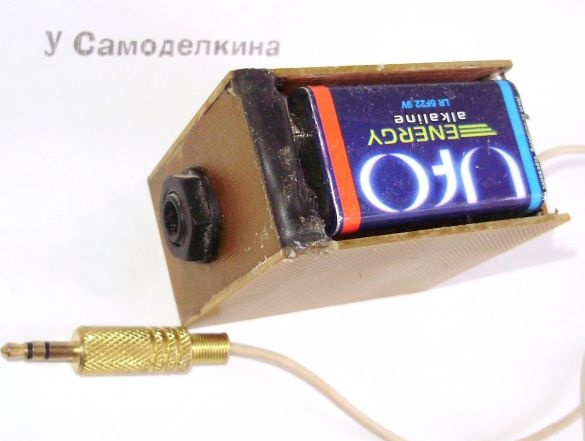
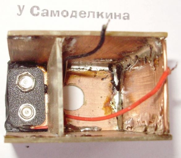
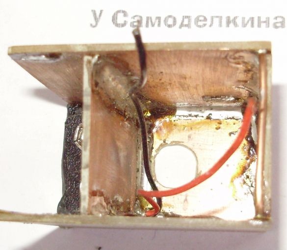
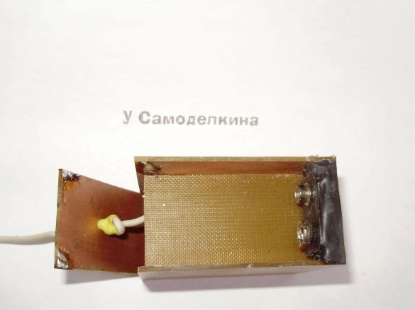
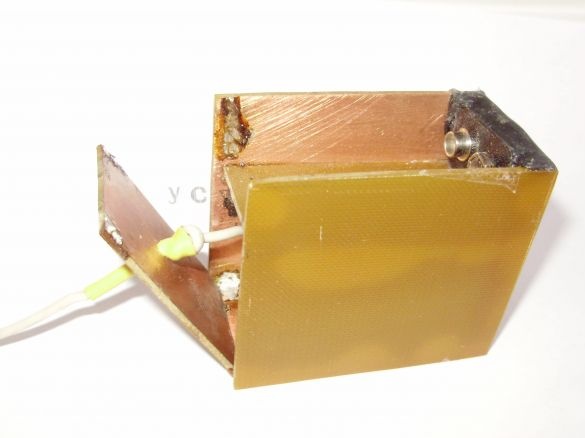
The case of the device is made of a single-layer PCB for full screening of the amplifier.
The dimensions of its parts are as follows:
- side walls 60x50 mm - 2 pieces
- front wall 50x30 mm - 1 piece
- back wall 46x30 mm - 1 piece. The size of 46 millimeters is not critical, it can vary from 50 mm to 35 mm. It all depends on how you want to install the battery.
- lower and intermediate walls 55x30 mm
The walls of the body are soldered together by solder. The foil on all walls should be inside the case. Try not to overheat the textolite, as the foil can easily peel off.
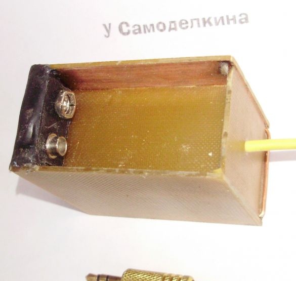
First of all, all the walls are welded together, except for the back. Then, holes are drilled for a jack connector with a diameter of 10 mm, a hole for power wires, about 3 mm in diameter, and the same in the back wall for a shielded wire with a mini-jack.
Also, in the place of attachment of the rear wall, a bracket of thick copper wire is soldered into which the bottom of the rear wall will be inserted.
After that, you will need to glue the connector for the "Crown". By the way, it can be taken from an already used crown, as I always do. This connector is glued with hot-melt adhesive to the back of the front wall. It is important that none of the pins of the connector touch the foil of the case.
After that, the power wires and the third wire connecting the case foil and the ground of the circuit are soldered to the circuit. A shielded output wire is also soldered, the circuit is installed in the housing and the back wall is sealed at the top on the sides.


