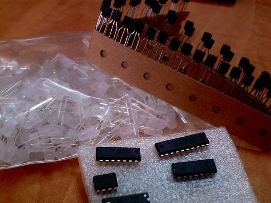
Materials:
- LEDs 144 pcs
- resistors 24 pcs (determined by the type of LEDs, in this case 91 Ohms)
- decimal counter 4017
- 6 pcs resistors (1 kΩ nominal)
- transistors 6 pcs 2N3904
- Long breadboard
- Arduino
- shift registers 3 pcs (74HC595)
- pin connectors

Step 1: How it works:
Usually the information in the LED matrix is divided into small parts, which are then transmitted one after another. Thus, a large number of pins on the Arduino are saved, and the program becomes quite simple.
Next, the time comes for 3 shift registers, they multiply the outputs and save a lot of pins on the Arduino.
On each register there are 8 outputs, only 3 Arduino outputs are used to control a huge number of shift registers.
The author also uses the 4017 counter to be able to scan rows. Using it, up to 10 rows are scanned, since the author has only 10 outputs, nevertheless only 2 outputs are needed.
As mentioned earlier, scanning is performed using this 4017 counter, by connecting one row to the ground at a time and sending data through the resistors to the columns.
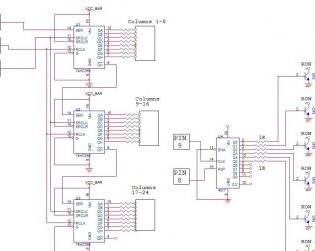
Step 2: Scheme
The only elements not shown in the diagram are current limiting resistors, since their rating directly depends on what type of LEDs are used. Therefore, their value must be calculated independently.
To calculate the values of 24 resistors, you can use the calculator
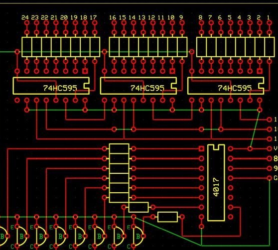
First, look at the specification of the LED in order to find out their forward voltage and their forward current. Information can be found immediately upon purchase. The circuit operates on a voltage of 5V. Accordingly, a power source with the same voltage is needed.
Also added is a control board mockup made using the Willard 2.0 tool.

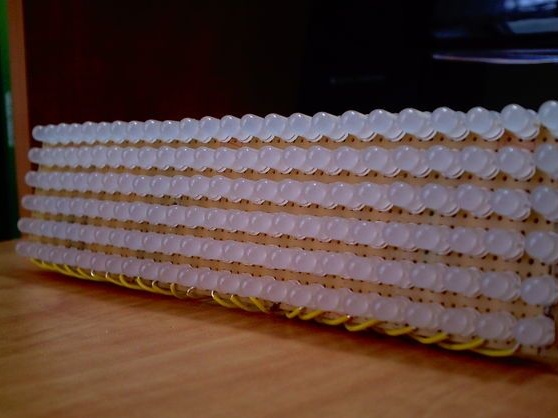
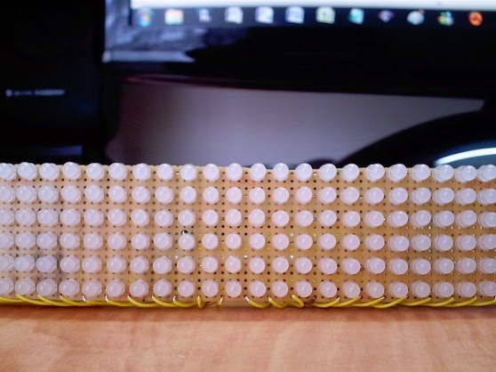
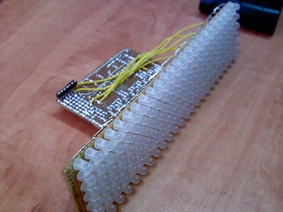
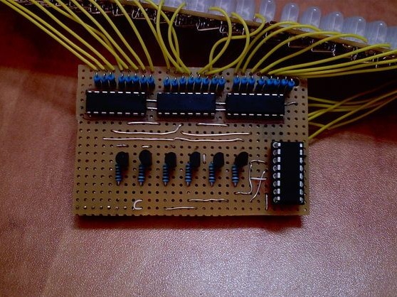
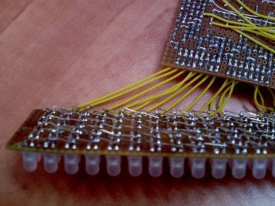
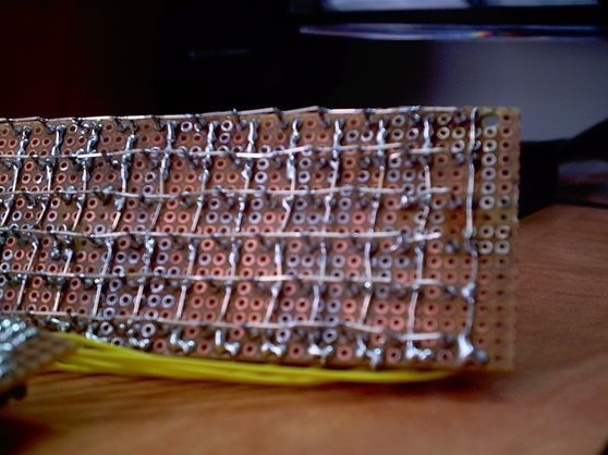
Step 3: soldering
Soldering such a large number of LEDs is no easy task if you do not know for sure how to do it correctly.
The author bends down the positive output of the LEDs towards the remaining conclusions, and a number is made, after which the inapplicable part of the output is cut off, and tries to make these connections as low as possible. This procedure is done for each positive conclusion.
At this stage, the negative conclusions are connected into a column and their soldering is inconvenient, since they have a positive row in their way. Therefore, the negative terminal is bent 90 degrees, and a bridge is made over the positive row to the next negative terminal, and so on for all other LEDs.
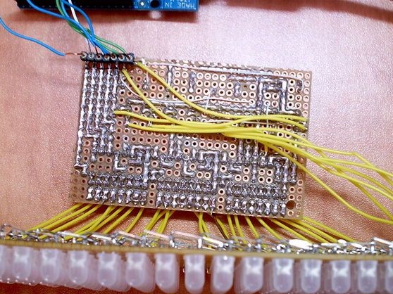
Shift registers and the remaining components can be soldered at the discretion of each separately.
Step 4: programming
The time has come for the last phase of the project.
The author before that wrote several similar programs. Therefore, he only had to add a program that would receive a word or a whole sentence from the IDE arduino monitor and then display it on the matrix. The code, of course, you can create your own or change this at your discretion.
An excel file is attached to the archive for the possibility of creating your own signs or symbols.
How to do it:
The desired character is created pixel by pixel (there is nothing complicated about it), and the output line is copied - #define {OUTPUT LINE}
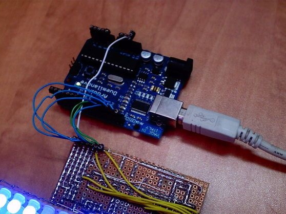
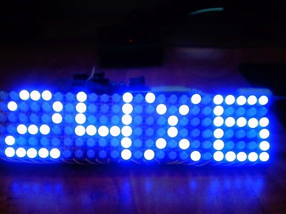
Step 5: the device is ready
The 24x6 matrix is ready, now it is possible to display anything on it. You can make new programs yourself or try to improve the interface.