

To create such a project, the author had to modify the launch system of his vehicle. The main connection is the IG conductor from the ignition switch, through which the supply voltage is supplied to the voltage regulator, and then to the Arduino to enable it, as well as enable the finger scan sensor. If the finger scan is successful, the system activates the relay block, and it controls the starter relay. Now you can get car. The sensor works for 10 seconds, and you can start it again by repeating the ignition start cycle. If in the allotted time the sensor did not detect a fingerprint or it does not match the set, then the start system will be disabled and the engine will not start.
Since each car has its own start configuration system, it is necessary to look into the electrical circuit before modifying the engine start system.
This article describes how to connect an anti-theft device to a 2-door Mitsubishi Lancer 2000 coupe.
Materials:
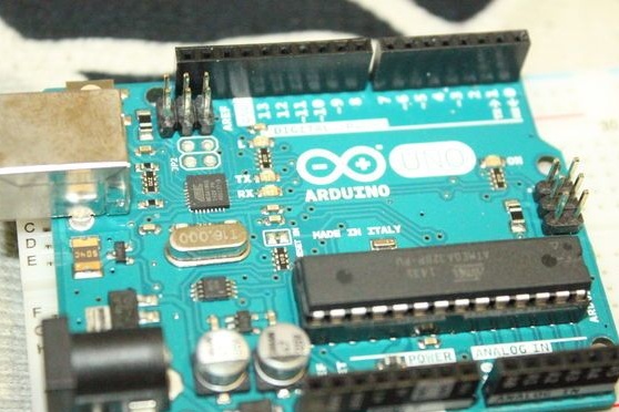
- Arduino Uno.
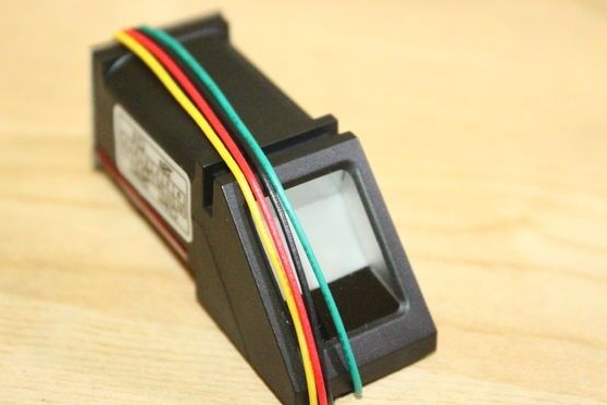
- Fingerprint sensor.
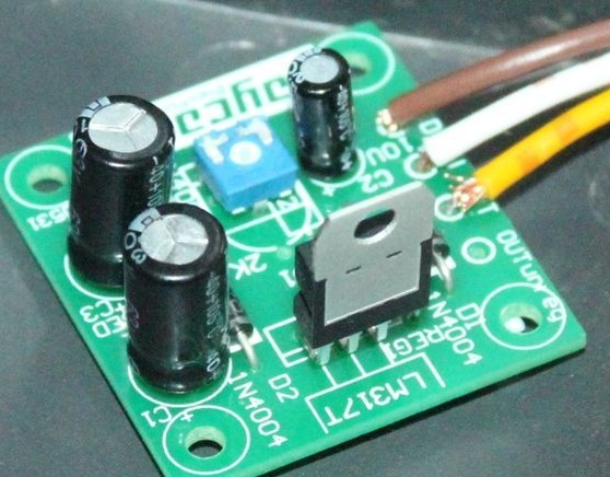
- Source of power.
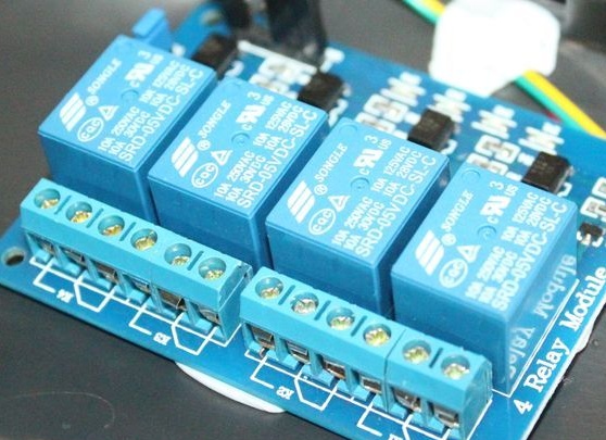
- Relay block.
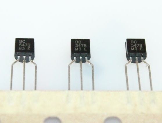
- NPN transistor BC547B
- Resistor 1 kOhm
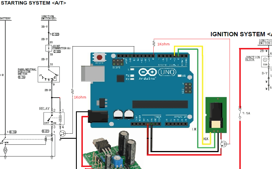
Wiring diagram:
The circuit is slightly modified in accordance with the components used. It should be remembered that it is valid only for this car model.
Step 1 Preparing the software components:
In the Arduino IDE, a library is loaded and added.
A file is downloaded from the blank.ino library in Arduino, which will serve as the interface between the sensor and the microcontroller.
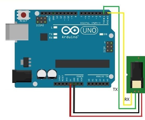
The program is installed, and the sensor is connected to the Arduino as shown in the diagram. Then the fingerprint is downloaded through the installed program.
Step 2 loading the main program:
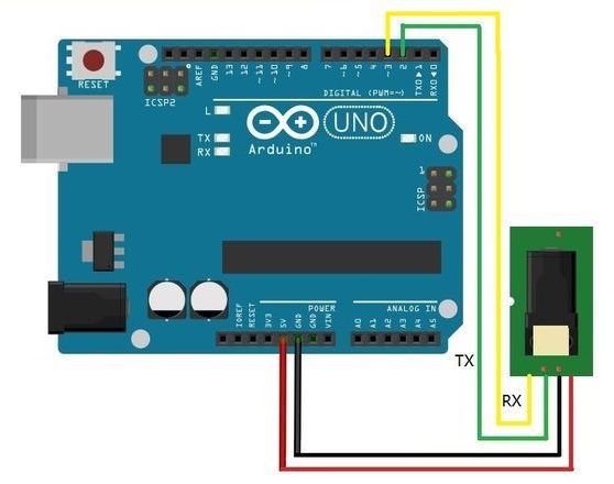
Now the sensor is connected as shown in the following diagram. After which the author proceeds to download the main program. An LED with a resistor is connected to pin 12.
The program will work primarily on the Adafruit Fingerprint training material. Only a sensor off timer of 10 seconds has been added to the program code. You can download the code under the article.
Step 3 assembly:
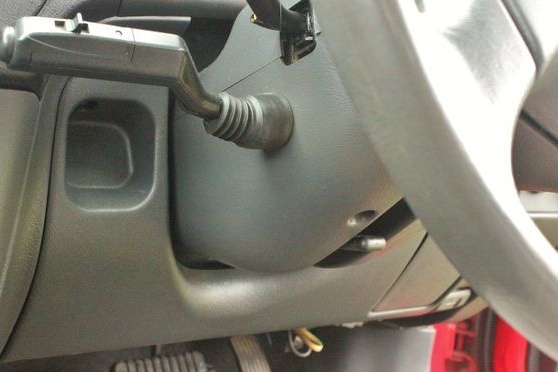
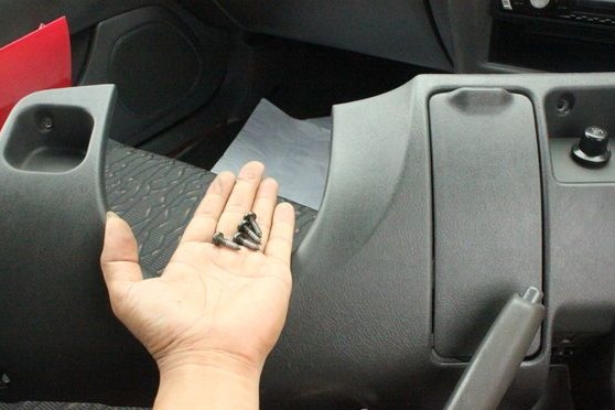
Part 1:
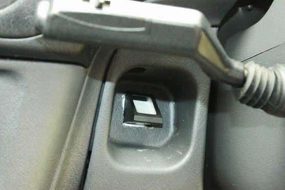
First, the screws under the dashboard are loosened. The lower part of the panel is removed, and in a free place it will be possible to place the sensor.
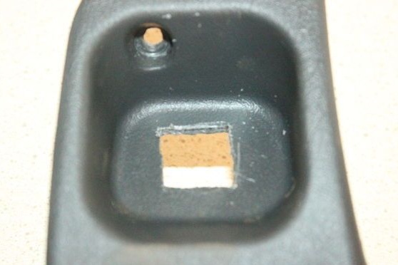
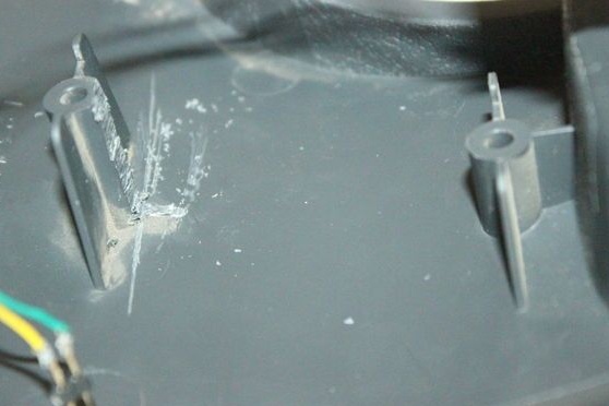
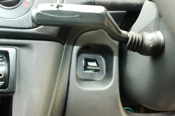
Part 2:
In the selected place for the sensor, a zone is cut out for its reliable installation.

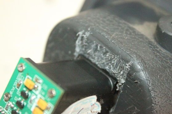
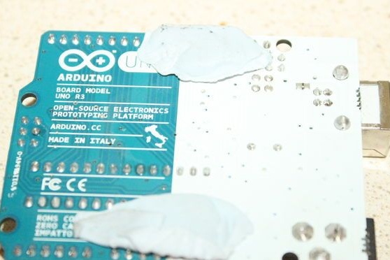
part 3:
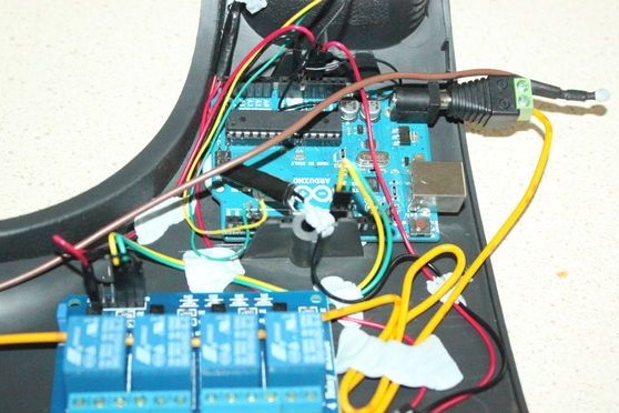
The Arduino board is installed behind the fingerprint sensor. The place for installing the Arduino was a bit undermined so that the board could take the correct position.
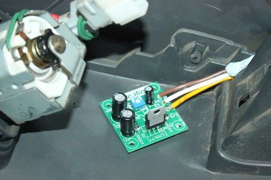
part 4:
An adjustable power supply is installed at the rear of the dashboard on the driver's side.
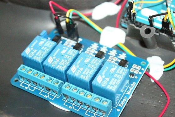
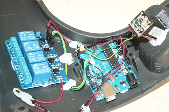
part 5:
The remaining components of the equipment are connected according to the diagram at the beginning of the article.
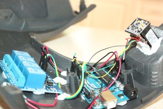
Step 4 installation:
The necessary wires are connected, and the device is installed under the dashboard. The author is convinced that there is no short circuit.
Video with the operation of the device: