
The signals from the sensor must be converted to voltage, for this purpose LM2917 is used. As the voltage increases, 30 LEDs will be switched on in series, which are connected through three microcircuits of the LM3914 type.
Specific in this article, the author replaced the ABS sensor with a stepper motor, because it can also generate pulses. In addition, such an engine also generates voltage, which increases with increasing speed. In this regard, the need to use a voltage regulator LM2917 has disappeared.
Materials and tools for manufacturing:
- stepper motor (can be found in the inkjet printer);
- wires;
- soldering iron with solder;
- microcircuits LM3914;
- tuning potentiometer at 47 kOhm;
- 31 LEDs;
- thick paper to create a display (cardboard);
- two resistors per 1 ohm;
- three resistors 2.2 kOhm;
- electrolytic capacitor 470 μF / 25V;
- two polypropylene capacitors per 100 nF;
- scissors and other little things.
Speedometer manufacturing process:
Step one. Install the speed sensor
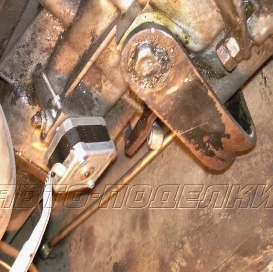
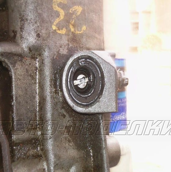
In order to make a sensor, you can use infrared detectors and LEDs, various sensors and so on. The author used a stepper motor from an inkjet printer for these purposes. Of the two, the largest was selected, which produces the most power and signals. The most difficult thing is to connect the engine with a cable, that is, put a stepper motor instead of the previous dial speedometer.
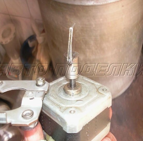
In order to connect both shafts, a piece of copper plate was used, which was cut to the desired size. It is inserted into the grooves and thus provides excellent coupling between the shafts.The engine itself must also be well fixed, since it is heavy and will ride around the cabin when driving, and this can violate the design. In the motor housing, you can drill a hole and then screw it in the right place with a bolt and nut.
Step Two Electronic circuit
After installing the stepper motor, 4 wires will appear that need to be connected correctly. The author took the first wire as a signal, and the second as a ground. During preliminary testing, the engine produces about 48 V. If you connect the motor to the transmission and spin it to the maximum possible value, it gives out 28 V. At the same time, we can conclude that the voltage increases linearly to the speed of rotation, which is very good and this voltage is enough to work speedometer.
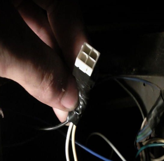
The voltage of 12 V is supplied from the battery, and the earth from the transmission. The signal is generated by a stepper motor. The fifth input of the LM3914 microcircuit will have to withstand a voltage of about 35 V. A 45 kOhm trimmer potentiometer is used to calibrate the signal. The speedometer is calibrated using GPS, which is in the phone or navigator.
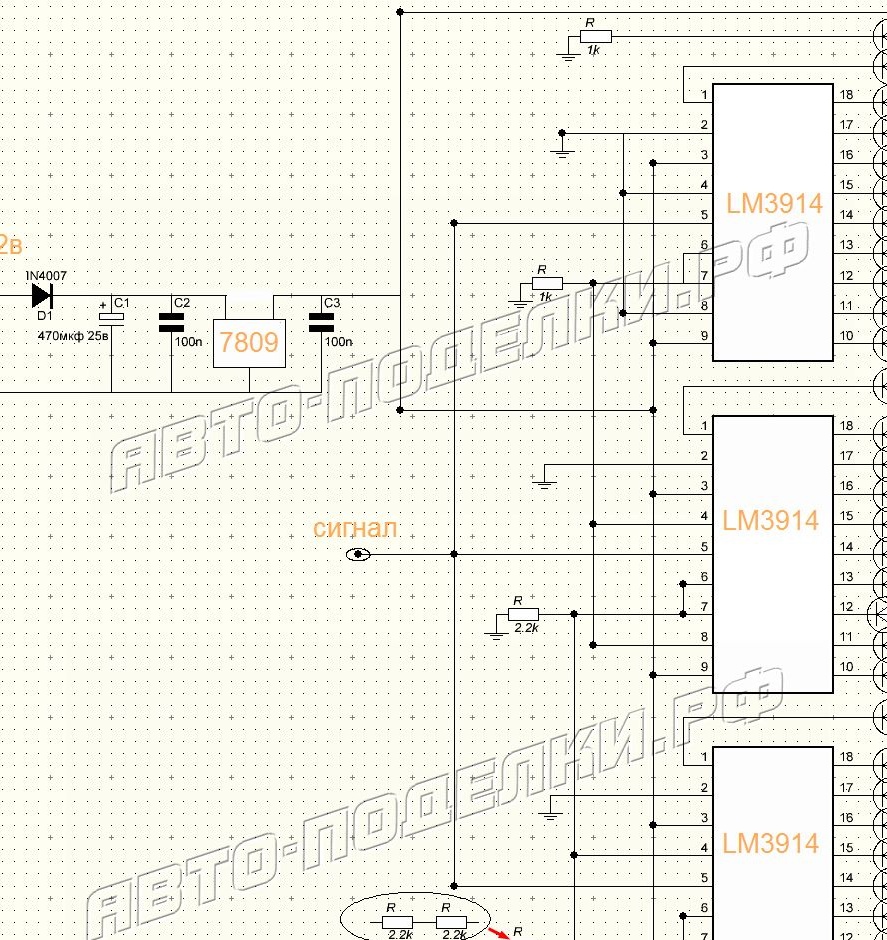
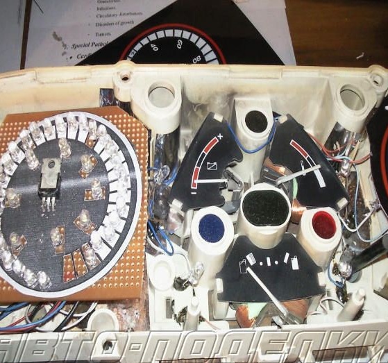
LM3914 chips are LED display drivers. Each of these drivers is needed to control ten LEDs, it can be either segmented mode or spot mode. Modes are switched according to the attached instructions. As for the controller 7809 (9V), it regulates the voltage.
Step Three Assembling the Speedometer
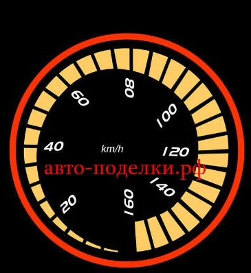
There should be 31 LEDs in total, the light is selected individually, the main thing is that they are bright. The author used bright white LEDs. You can make the tape multi-colored, for example, put red at the end, which will indicate a high speed of movement, and first green or blue LEDs.
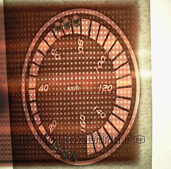
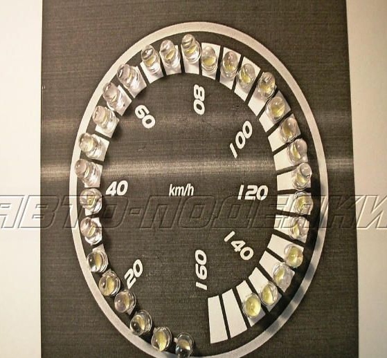
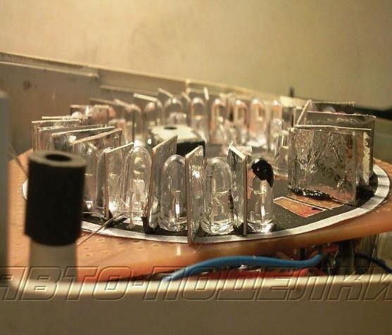
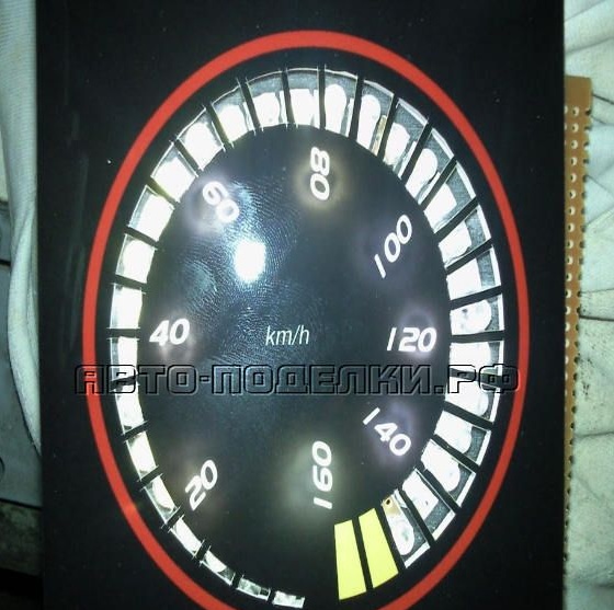
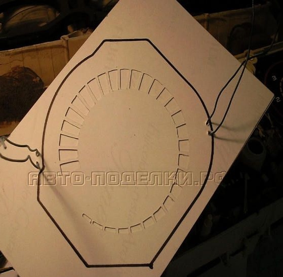
The first LED should be on continuously when a + 12V power is connected. The remaining 30 will be included in series with increasing vehicle speed. The basis for the LEDs is made of cardboard, rectangular compartments are cut out opposite them, onto which thinner paper is then glued. When the LEDs work, the light will only pass through thin paper, forming the effect that can be seen in the photo. Paper can be painted in any color. Naturally, later this whole design is put in place of the insides of the old arrow speedometer.
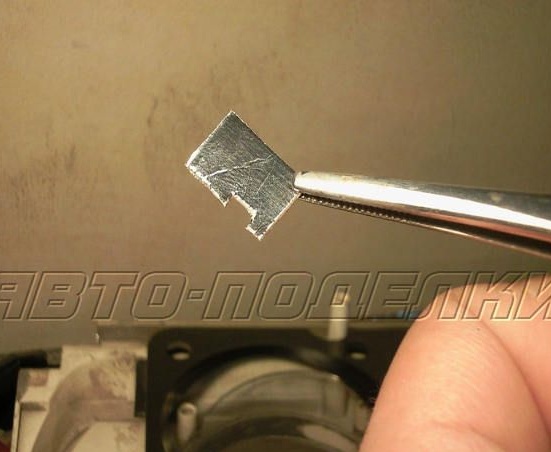
Between the diodes, you need to make partitions so that the light does not propagate throughout the tape. It is best to use aluminum, it will perfectly reflect light.
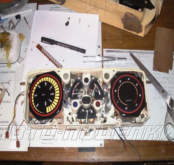
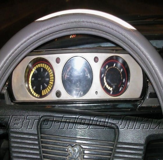
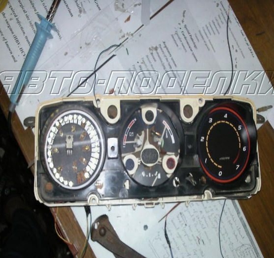
That's all, now it only remains to install the speedometer and connect it. In the photo you can see that the author has replaced such homemade and tachometer.