
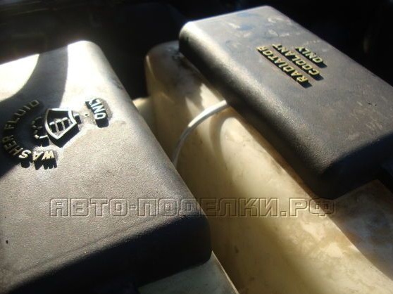
The cooling system is one of the most important elements of the car. Indeed, if a coolant leaks or its circulation is disturbed, the engine instantly overheats and fails if it is not turned off in time. In this regard, it is advisable to monitor this system. Although in any car and there are coolant temperature sensors, they will never tell you about its leak. After all, if the fluid leaks, then perhaps somewhere there was a breakdown, which urgently needs to be eliminated. Thus, the device proposed by the author will be a great addition to any car that will make it more reliable and save nerves.
Materials and tools:
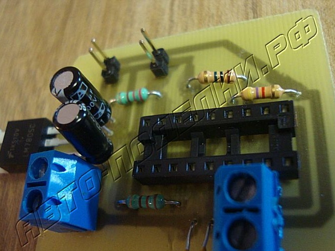
- two LEDs (green and red);
- printed circuit board;
- JAL compiler;
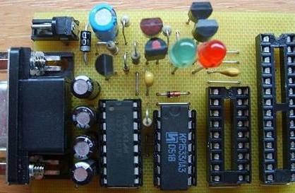
- microcontroller PIC16F88;
- wires;
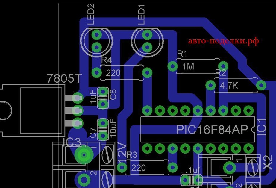
- resistors, capacitors (the rating is indicated on the diagram);
- soldering iron with solder;
- fuse.
The manufacturing process of the device:
Step one. Electronic scheme
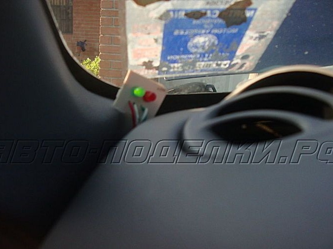
The indicator works on a PIC16F88 type microcontroller, it uses JAL software. Firmware for the indicator is attached to the article. In total, the system has two LEDs, one red and one green. When the coolant level in the expansion tank is normal, the light will turn green. If it falls below the established norm, the red lamp lights up.
The system should turn on only when the ignition switch is turned on, and connect only through the fuse.

In total, the system is able to work in two modes, this is sleep mode and watch mode. In the first case, the system will work continuously with the ignition on. In the second, the indicator will only start occasionally, test the system and then turn off again. This option is preferable, since less energy consumption.
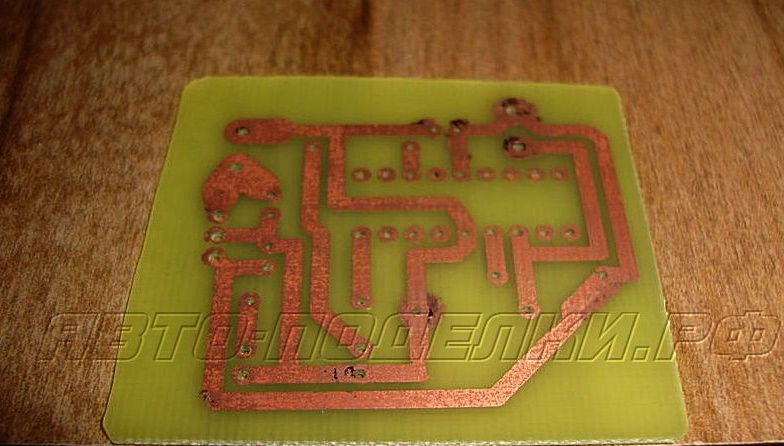
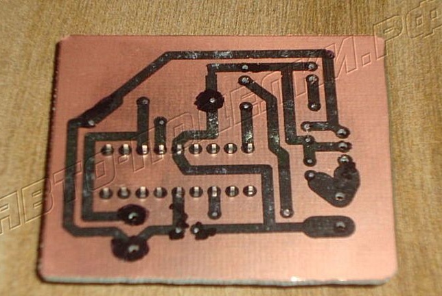
The printed circuit board is easiest to manufacture on a laser printer. Subsequently, the tracks are transferred to copper using a laminator.
Step Two Indicator software
Since the system runs on a microcontroller, you need to download software to it, it has the JAL format. A special compiler and PIC programmer are used to install it. You can use one of two modes in the system, these are watch and sleep modes.
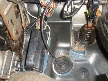
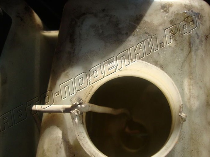
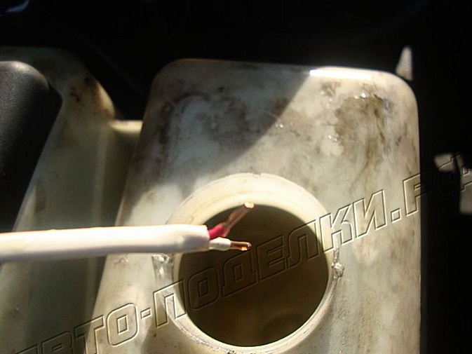
Step Three Install the sensor
To connect the board, you need several wires. One wire is a plus, which is connected through a fuse to the ignition switch. The ground wire can be connected to any metal element of the chassis. Two more wires are needed in order to supply power to the LEDs and provide their ground. Well, two more wires are connected to the coolant sensor.
The author has a 99-Ford Explorer car, plus he connected it with a No. 12 fuse, it is used to operate the wiper pump.
Finding the right fuse is very simple, for this you will need a voltmeter or an ordinary 12V bulb with two wires. One wire connects to the ground, and the second you need to find a plus on one of the fuses. It is important that the plus is turned on when the ignition is turned on, and when the key is turned to the “Off” state, the plus is turned off. Otherwise, the system will work continuously, landing the battery.
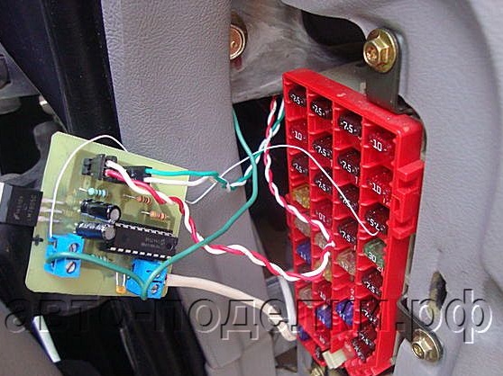
Now all that remains is to connect and conduct the wiring. The wires must be drawn so that they do not touch the engine elements and do not hang out. They need to be wound with electrical tape to a common wiring harness or fixed with plastic ties.
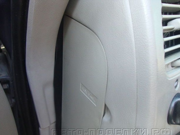
The board is hidden in the console, and the LEDs can be displayed anywhere at your discretion.
Step Four Device testing
When the ignition in the car is turned off, the LEDs should not blink, if they blink, then the system is connected to the wrong fuse. When the ignition is turned on, the green LED should blink, this will indicate that the sensor is immersed in the coolant and the system is operating normally. If the lights do not light, it is possible that +12 V is not supplied to the system. You also need to check if the earth is present. Even the LEDs may not light up for the reason that their polarity is incorrectly selected.
If it turned out that when turning on the red LED blinks, and when the probe is pulled out, the green blinks, then the LEDs were mixed during assembly. If after that the red still flashes, then a short circuit is present in the probe. If the green LED also starts flashing, you need to strip the probe wires more strongly, or you can arrange the ends of the wire closer to each other. If this does not help, you need to increase the value of the resistor 1 mOhm.
In addition, the indicator will be activated if the coolant is already too old and needs to be replaced. It will increase electrical conductivity due to incipient corrosion. Well, of course, it is important not to forget that defects may occur during soldering, and in this connection the board itself should also be checked.