
This project is ideal for those who often forget to feed their fish. Or simply not always able to do it on time. Having made such a feeder, you can not worry about your little pets, and even feel free to leave for a while.
Materials:
- Arduino UNO or another compatible microcomputer.
- Power adapter 9V or 12V.
- A 5V stepper motor from an old floppy drive.
- Smooth partition (used from the tool box).
- Lever switch from a landline telephone.
- The case from the hard drive (serves as a container for feed).
- Smooth plate (e.g. plastic ruler).
- Tripod from a CCTV camera.
- Resistor 10 kOhm.
- Mechanical AC Timer.
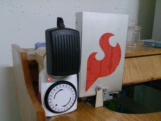
Step one. Case Assembly:
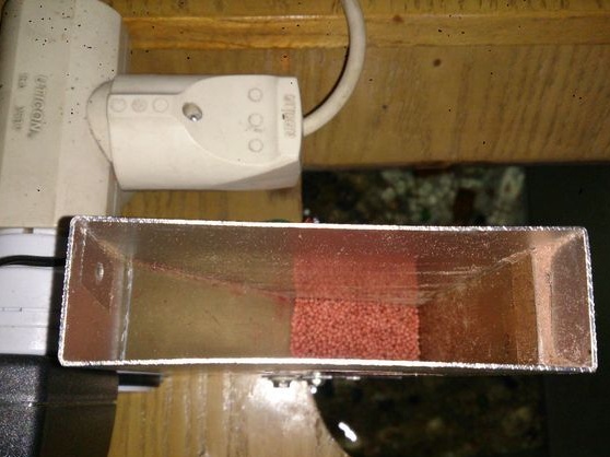
The assembly design is shown in the first figure. A hole is cut out on one side of the hard drive enclosure. For this part of the feeder, you can even use a plastic bottle, however, you will need to come up with a support for it so that it is held upside down.
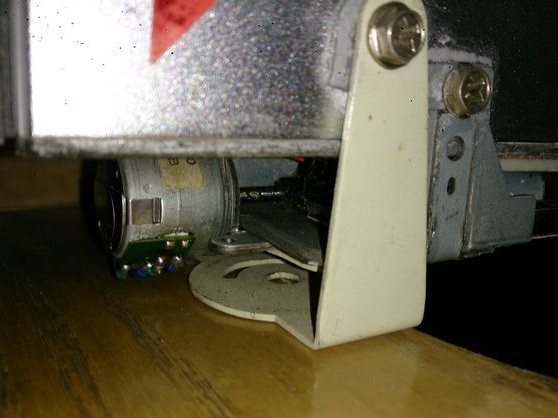
The author uses a tripod from a CCTV camera, since it has an ideal height for installing a stepper motor under it. All that remained was to drill a hole in the casing.
A 5V stepper motor with a drive mechanism used to move the drive lenses was used to move the cover. A smooth partition from the box was placed on top of the lens holder, below the hole where the feed pellets should exit. To do this, it is also recommended to use a broken ruler. Leave one millimeter from the bottom of the hull so that the feed pellets can pass through the closed lid.

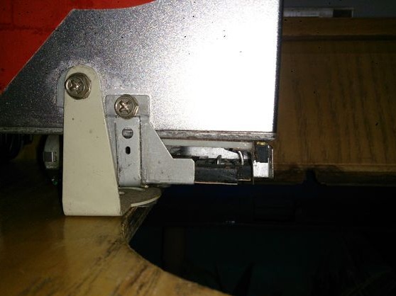
Step Two Modification of the body:
The following diagram shows how the feed should pass through the hole correctly so that the pellets do not linger in the feed exit angles.
After two days of use, the author realized that some of the feed was stuck, but did not come out as intended. That is why we needed a ruler or any smooth plate that fits into the container and in the shape of the letter V.

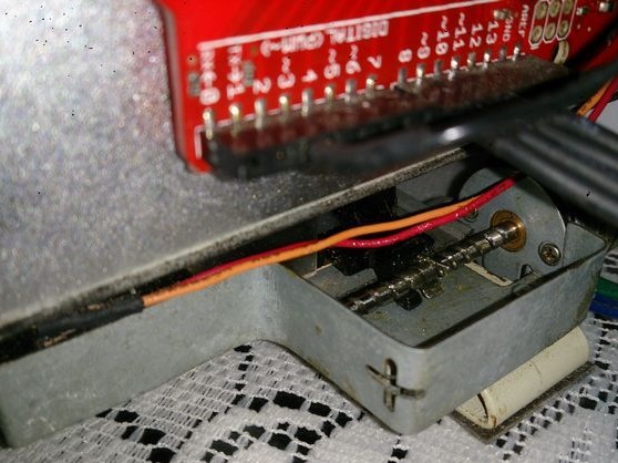
Step Three Electronic part of the feeder:
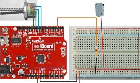
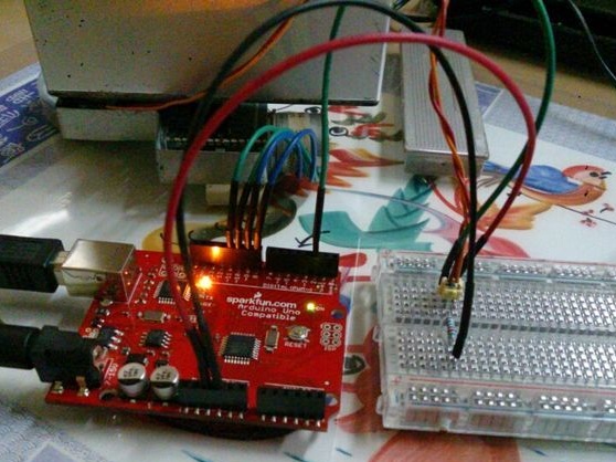
A stepper motor, a 10 kΩ resistor and a switch are installed as shown in the diagram below. To facilitate understanding of the operation of the circuit and testing, a breadboard is used, it is missing in the final assembly (example in the last photo).
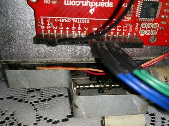
Four motor wires connect to digital pins 8-11. One foot of the switch to the 5V power output. The second leg, in turn, is connected to the ground using a 10 kΩ resistor, and is also connected to digital pin 2.
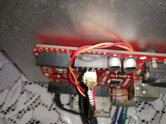
The switch is placed in front of the movable cover, and the metal part is bent, thereby forming a stopper (red and orange wire in the third photo). When the switch is moved forward and presses the stop, the Arduino will register a HIGH value and stop the engine.
The board is attached to the back of the case with electrical tape, and the plug with a timer on its side. They are used to balance the case so that it stays in the correct position.

Work test homemade without food container:
The following video shows the operation of a fully assembled device. As you can see, the first feed output is correct. At the second exit of the feed, it can be seen that if the granules are stuck and the lid does not close properly, then it will move forward and backward until it closes correctly.
Program Code: