Such a device can help control air quality, as well as warn the owner of a gas leak or the presence of combustible gases. For additional functionality, the detector includes a humidity and temperature sensor. This mini-station will be able to detect all major atmospheric pollutants (carbon monoxide, nitric oxide, sulfur dioxide, ozone and particulate matter), except for sulfur dioxide.
Due to the fact that the sensors used have different prices and their parameters differ from one another, their calibration took place at known gas concentrations to the author.
Materials:
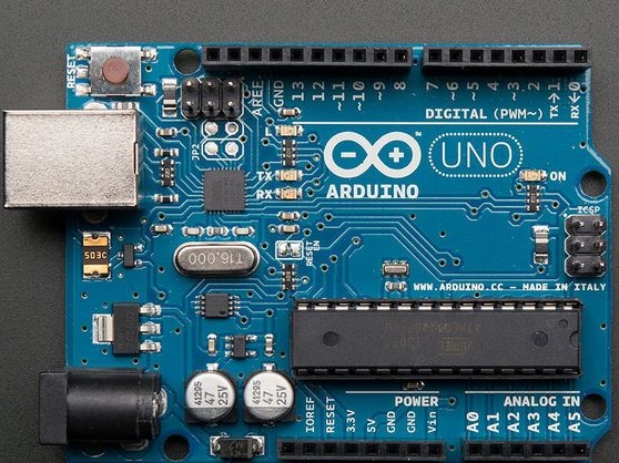
- Arduino Uno
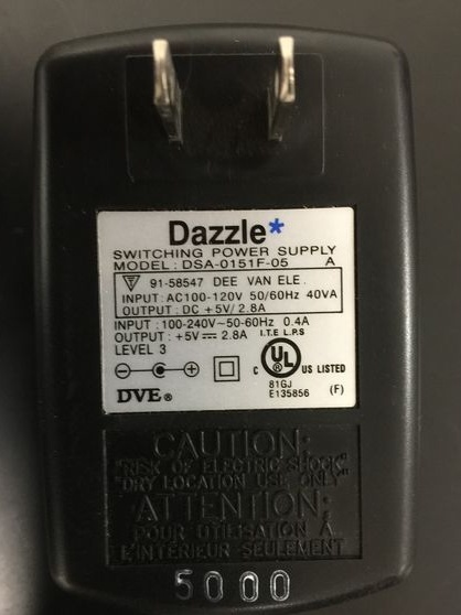
- 5V power supply
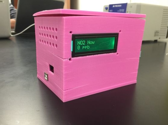
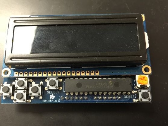
- LCD shield RGB 16x2 LCD shield
- Gas sensor MiSC-2614 (Ozone)
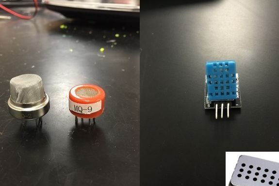
- Gas sensor MQ-9
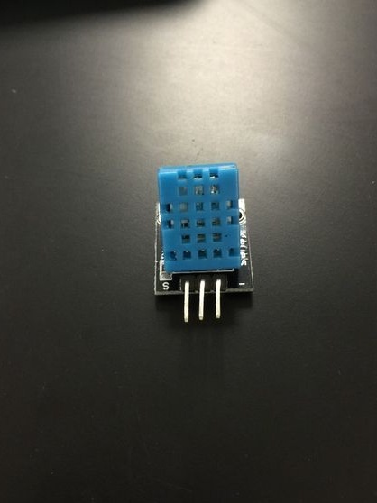
- Keyes DHT11 humidity and temperature sensor
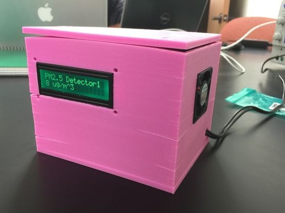
- Shinyei PPD42 particulate matter sensor
- Gas sensor MQ-2
- Gas sensor MiCS-2714 (NO2)
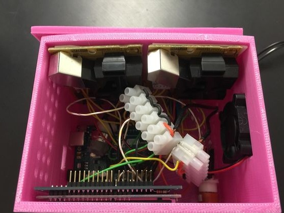
- Access to the 3D printer (for the case, you can use the existing plastic or wooden box)
- Bread board
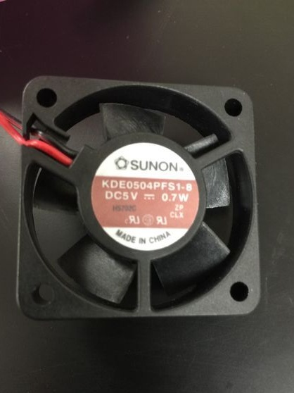
- 5V fan
- Conductors of caliber 24 (0.511 mm) 10 - 15 pcs.

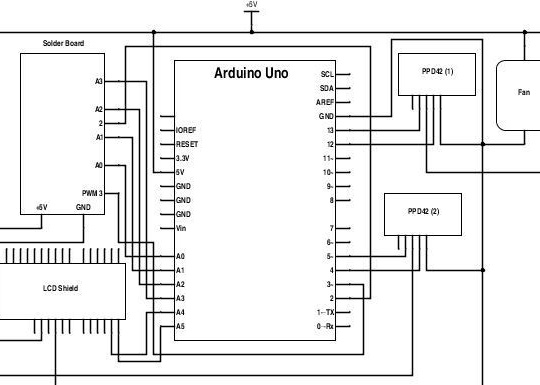
Electric circuit:
This diagram shows a general diagram of the operation of the device to represent what this detector is. The author asks you to pay attention to the fact that most ports with sensors can be changed, but then you need to change the program code.
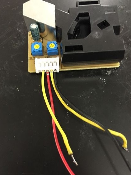
Step one. Particulate sensor.
Two Shinyei PPD42 sensors are used to collect particulate data.
Each of them has two outputs: left yellow for small solid particles, and the second for large particles. The outputs will be connected to Ardiuno with a 5V supply voltage, as indicated in the general diagram.
Each of the sensors uses an LED and a photodiode to measure the concentration of particles in the air.
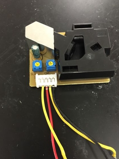
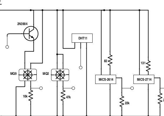
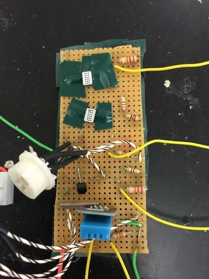
Step Two Gas sensor board.
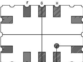
Below is a diagram of the printed circuit board of gas and temperature sensors with humidity. The author made a printed circuit board on his own and recommends also to those who will be involved in this project, and notes that the circuit board may differ physically from the one indicated on the diagram.
Step Three NO2 and ozone sensors.
IN homemade use surface mount sensors MiCS-2614 and MiCS-2714, they detect ozone and ozone dioxide in the air.
Each sensor in its sensor element uses an internal resistor. The diagram shows the location of the measuring resistor between the terminals K and G. An ohmmeter was used to determine their correct location. The resistance of the resistor is within kOhm.The sensors also have a heating element between terminals H and A, which maintains the temperature of the sensor element. The heating element has a resistance of 50-60 kOhm.
Further, 82 kOhm and 131 kOhm resistors are installed in series with the sensor elements on the breadboard.
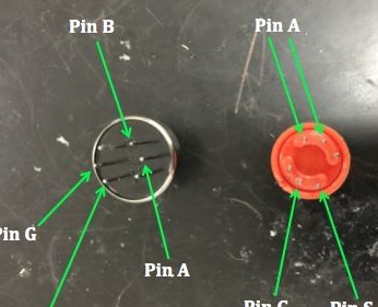
The fourth step. Gas sensors.
The author uses gas sensors MQ-2 and MQ-9, which measure toxic gases. The sensors use a gas-sensitive resistor to detect toxic gases, and use their heating element to set and maintain the desired temperature of the sensor.
Sensors are installed according to the layout of the circuit board. The MQ-2 sensor is connected by terminal A to a 5V power supply, terminal G to ground, terminal S to ground through a 47 kOhm resistor. The MQ-9 sensor is connected in a slightly different way: pin A to the transistor, B to 5V power, pin G to ground, and pin S to ground through a 10 kΩ resistor.
Step Five Humidity and temperature sensor.
This sensor is a must, since monitoring humidity and temperature is a very important part in determining gas concentrations. Increased values of humidity and temperature will greatly affect the accuracy of measurements for both of these parameters can be monitored with a single sensor. Its connection is as follows: the left terminal is connected to power, the middle terminal is a signal output, and the right terminal is connected to ground. The signal from this sensor will be sent to the Arduino digital port.
Step Six Fan and power supply.
If you look at the diagram of the entire project, you can see that only one input voltage of 5V is used. This homemade product uses a regular network adapter. For proper operation of the device, and to prevent overheating, a 5V case fan is used.

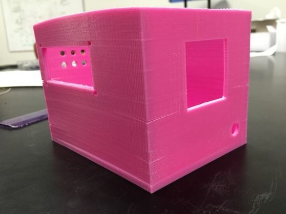
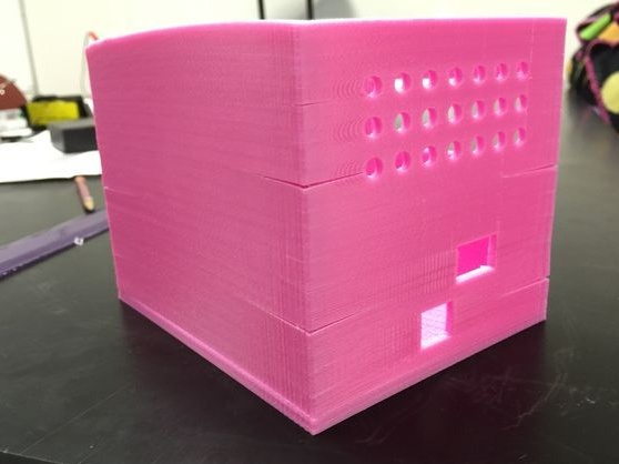
Seventh step. Body.
The case can be made from improvised materials such as wood, metal, plastic. The author used a 3D printer, a file for printing is attached at the bottom of the article.
Step Eight. Program code.
The code for extracting data from the detector is attached under the article. The code prints on the monitor the sensor values, Shinyei PPD42 signals, and humidity readings with temperature. Also, data is displayed on the LCD display.
For the operation of the device, the libraries of the humidity sensor and LCD shield are loaded.