
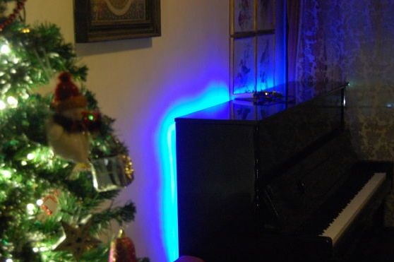
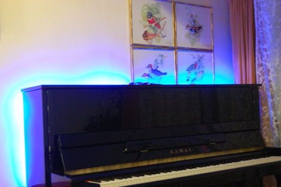
After some experiments by the author with LEDs and Arduino he came up with the idea of creating a piano backlight from RGB LED strips. The light from the LEDs is reflected from the wall behind the piano, thereby creating an excellent lighting effect. The project also uses an acoustic sensor, under its control, the tape changes color depending on the volume of the sound of the instrument.
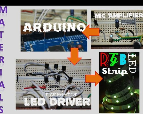
Materials:
- Arduino
- 2 meters of RGB LED strip
- Transistors 6 pcs (2N2222)
- Resistors 6 pcs (220 Ohms)
- Operational amplifier LM324 (you can use LM358)
- Electret microphone
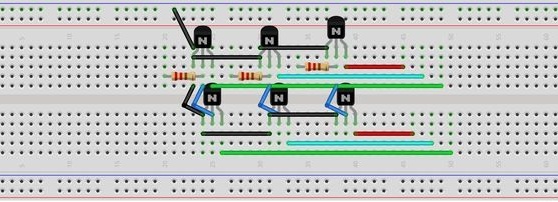
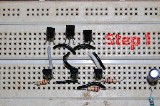
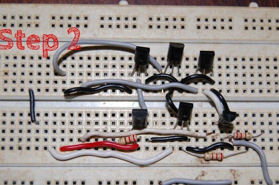
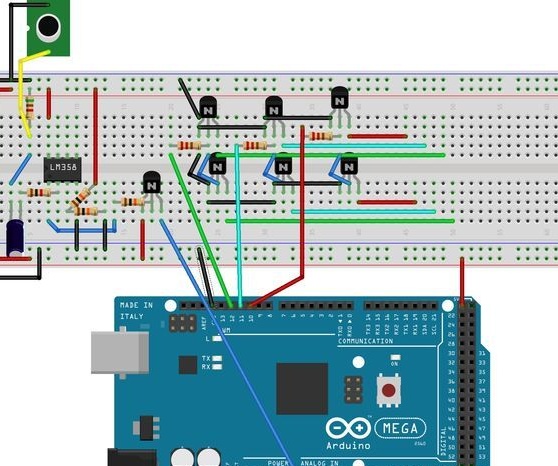
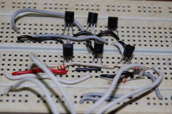
Step one. Transistor circuit.
Transistors boost the current from the Arduino to tape. The author uses transistors 2N2222, as they are designed for current up to 600 mA. This is enough for the brightness of a meter LED strip. So, for a length of 2 meters, six transistors are required (three for each). Below you can see the assembly photo and diagram.
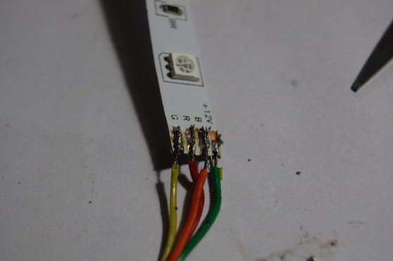
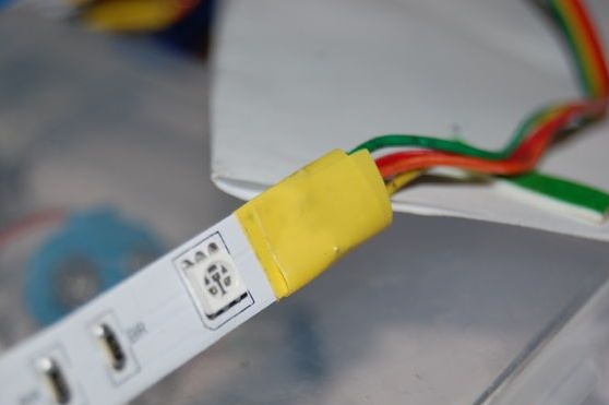
Step Two LED strip preparation.
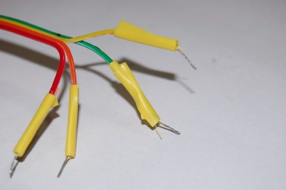
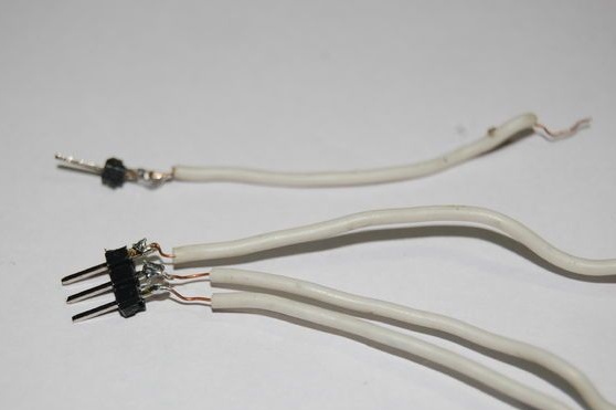
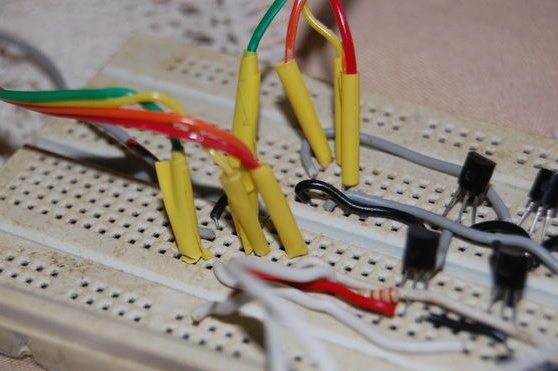
The project uses two RGB tapes with a length of 1 m, the length of the common tape is 2 m. The preparatory work begins with a 1 meter tape. The wires are soldered according to the first photo, the soldering place is isolated. Insulating the wires as in the third photo will help connect them to the breadboard.
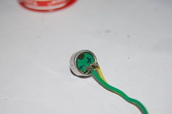
Step Three Electret microphone.
First you need to determine the polarity of the microphone, which conclusion is positive and which is negative. For this, the author used a device to control the integrity of the circuit, and found out which of the conclusions is connected to the external casing. This conclusion is earth, and the second is positive.
15 cm wires are soldered to the microphone as shown in the photo, it can be seen that the green wire is used as the ground wire, and the yellow one as positive.
The fourth step. Microphone gain circuit.
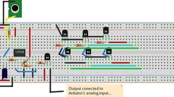
Since the microphone itself transmits a rather weak signal, an operational amplifier was required to build up the signal to the Arduino so that signals from its analog output could be read.
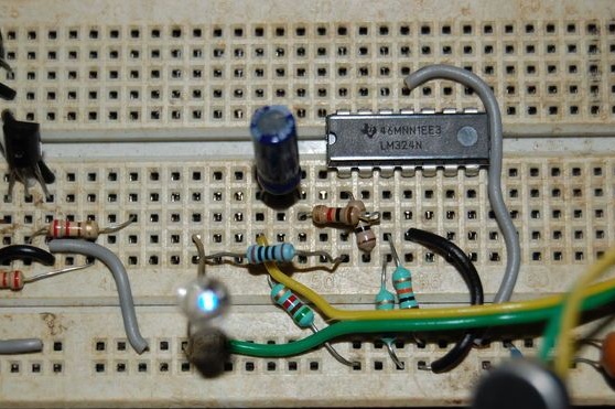
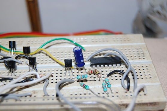
The author uses an operational amplifier LM324, which has four channels, however, only one is used in the project. It is better to use a two-channel amplifier LM358 with a similar circuit, only the power leads differ. Below you can see the diagram, and photos for this circuit.
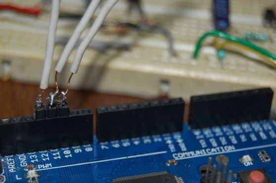
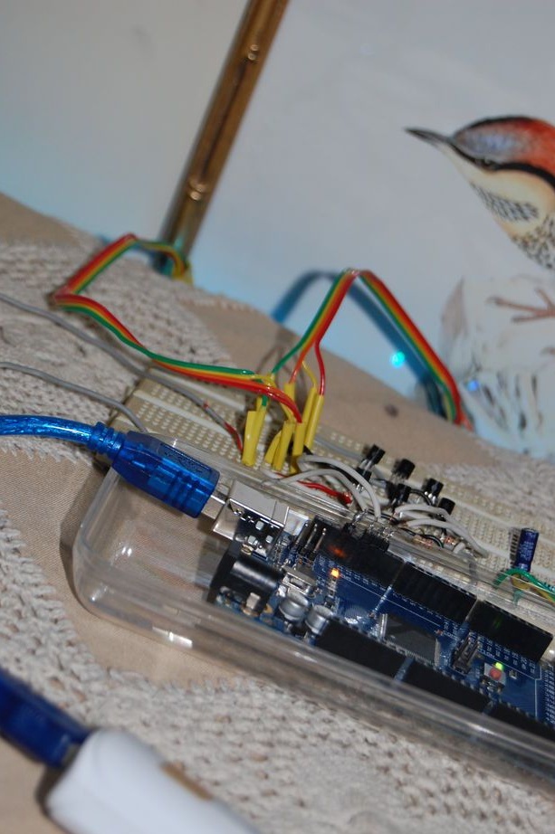
Step Five Connection to Arduino.
To connect, you need dad-to-dad connecting wires, the author made such jumpers independently (second photo), using several jumpers and a contact connector. The breadboard is connected to the Arduino microcontroller according to the diagram and photo.
Step Six Tape testing.
Before continuing to work on the project, the author decided to make sure the assembly was correct and check the operation of the RGB tape with the master circuit. A sketch attached under an article is uploaded to Arduino.
Note from the author: if you are using a non-Mega board (for example, like Uno), you need to replace the output terminals for the LED with a PWM. For Uno, the compatible outputs are 2, 3, and 4.
Seventh step. Testing the microphone circuit.
This procedure is required to verify the operation of the microphone gain circuit. To the output 1 of the amplifier, the author connected an LED, and monitored changes in its brightness depending on the sound volume.
Using Arduino for the test:
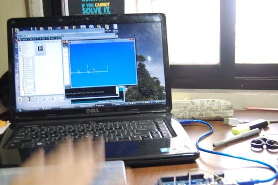
This is a more accurate verification method. The analogReadSerial sketch (File> Examples> AnalogReadSerial) is loaded into the microcontroller. Next, Processing opens, where the author copies the code graph_line.pde (the code in the archive under the article), and launches the program. When the Arduino sends A0 output values via USB, the program determines these values on its chart with a range from 0 to 1023. By making various noise and increasing its volume, the signal steepness increases, and the chart confirms this.
Step Eight. Program code.
The code from the piano_new_way.ino file is copied to the Arduino IDE window. The author recalls that in the non-mega board, you should change the outputs of the LED output to 2, 3 and 4.

Step Nine. Install tapes on the piano.
To fix the LED strips to the back of the piano, the author used ordinary and double-sided tape. It is used in order not to damage the surface of the piano, and to be able to remove the tape in the future. The tape is fixed so that the wire connectors for each of them are accessible on top of the tool.
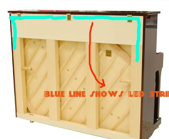
Step Ten Connecting LED strip.
Each tape is connected to a transistor driver circuit on a breadboard, according to the photo below. You can also use the diagrams from the previous steps. As a rule, each channel is connected to the collector of each transistor.
Step eleven. The final part.
The 12V positive wire from the power source is connected to the positive wire of each tape, and to the “Vin” of the Arduino board. The ground wire connects to the Arduino ground.
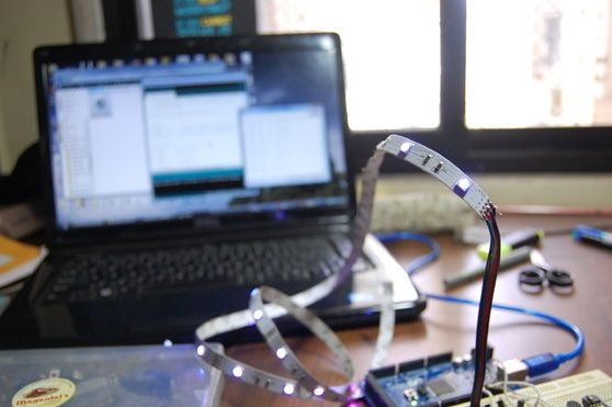
Power is now supplied, and the RGB tape lights up behind the piano in bright fire. Playing the instrument changes the color of the LEDs, depending on the sound volume.
This project is not necessary to use only with a piano, it is also suitable wherever there is music, and you can place them anywhere in the house.
Video showing the change of colors when playing the piano: