This project is perfect for your work area, or the garage where do you develop homemade. The finished project in one module includes many functions: a clock with a date and time display, a stopwatch, an alarm clock, motion tracking (for automatic shutdown when you are not in place).
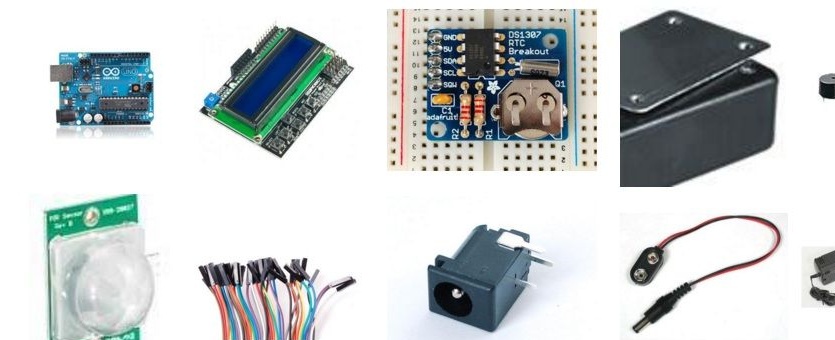
Materials:
- Arduino Uno
- LCD shield (with buttons, the project uses a shield from DFRobot)
- Box for housing
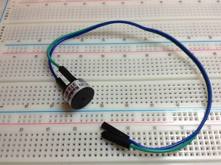
- buzzer
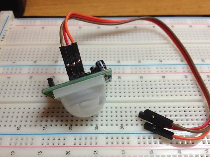
- Infrared motion sensor (PIR)
- Connecting wires (mother / mother)
- jack 2.1 mm
- Adapter for crown 9V 2.1 mm / 5.5 mm
- Krona 9 V
- Real time clock
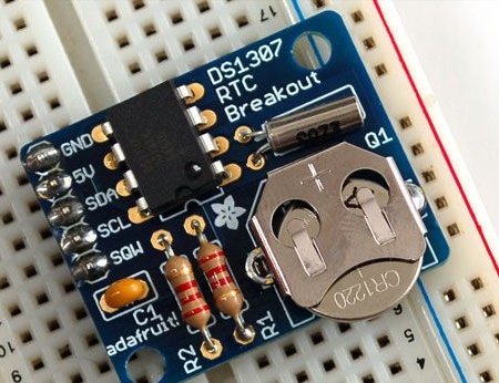
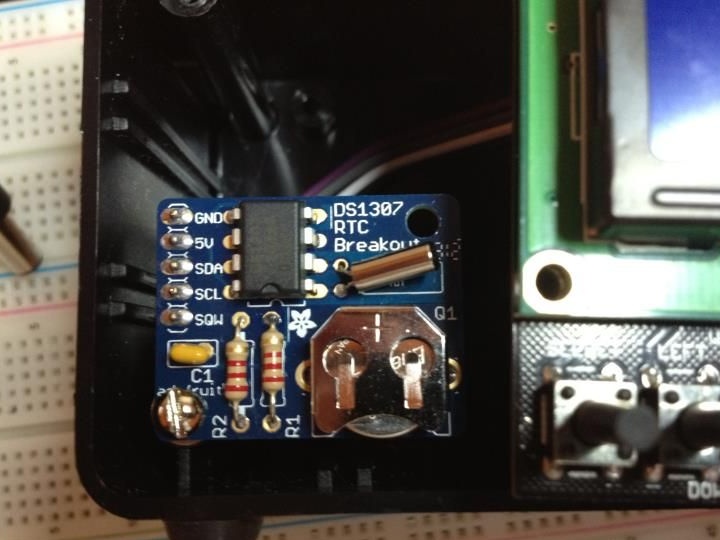
Step one. Real-time clock module.
Often the clock module is supplied in the form of a designer, which you have to assemble yourself. Usually the assembly does not cause problems, plus manufacturers issue instructions for assembling their module. Also, the battery comes with a watch, it will last for more than three years.
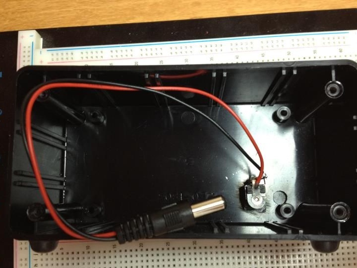
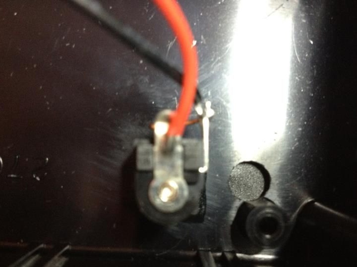
Step Two Power connector
To simplify connecting the design to the Arduino, the author uses a 2.1 mm jack with soldered contacts. A hole is made in the box, and the jack is fixed with glue. Thus, connecting to the Arduino will not be a problem. The crown will simply be installed on the back of the box. If you take a closer look, you will notice another hole in the box. It does not need to be done, it is simply an unsuccessful attempt to make a hole, the jack simply did not fit into it.
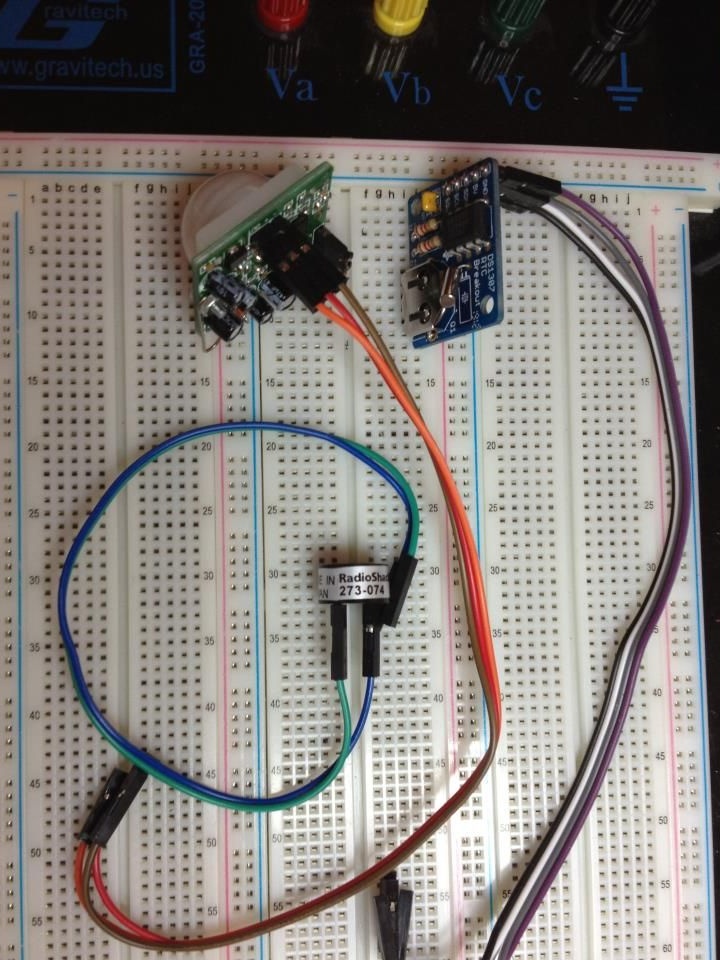
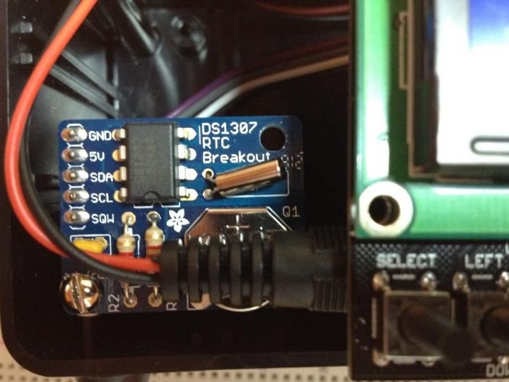
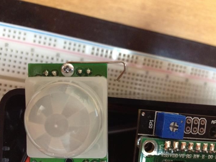
Step Three Wire connection.
The author purchased multi-colored wires mother / mother. They cost inexpensively, but greatly facilitated the assembly process. The conductors are connected to the buzzer, PIR motion sensor, clock module, so that later all this can be connected to the LCD shield.

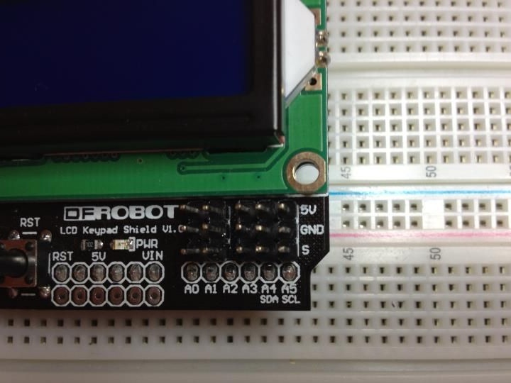
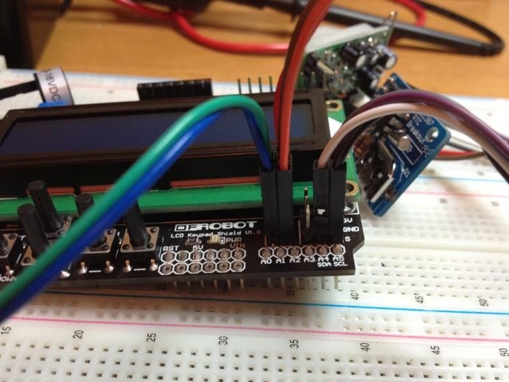
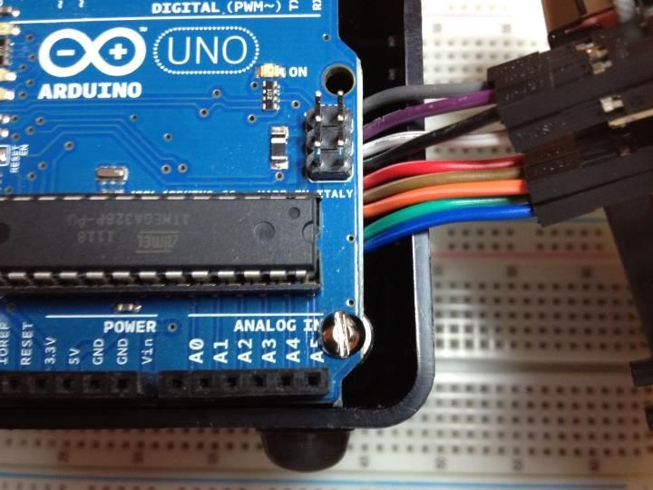
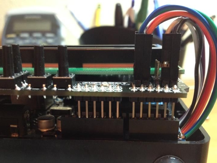
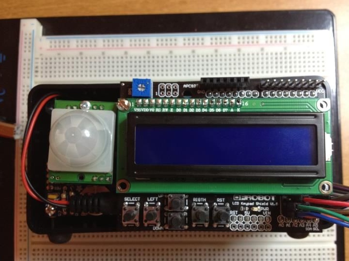
The fourth step. Connection to LCD shield.
On the shield there are 5 rows of contacts, their pins on the Arduino 1-5, respectively. There is a contact for 5 V and GND, it was all used to connect. To transmit data with a buzzer, sensor and real-time clock, Arduino analog pins are used. The sensor with the clock, of course, was connected to ground and power.
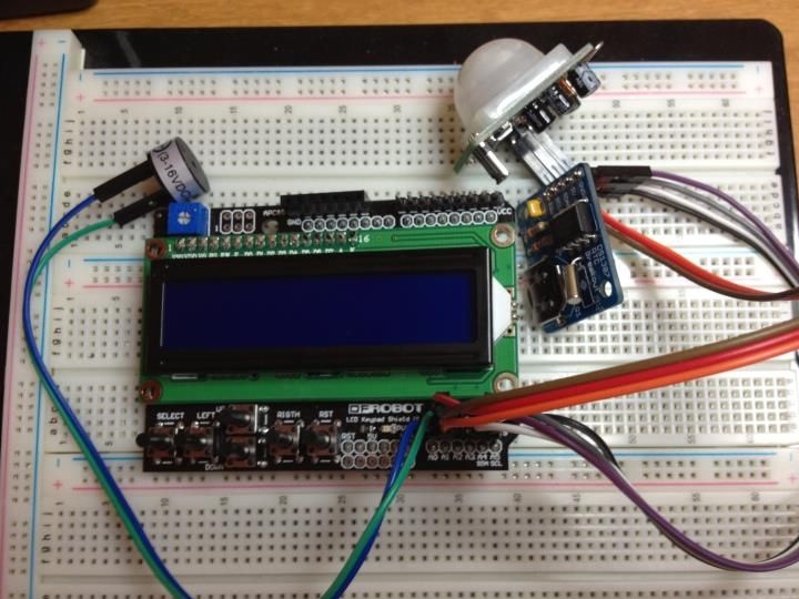
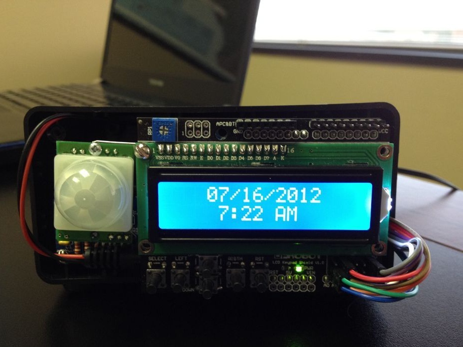
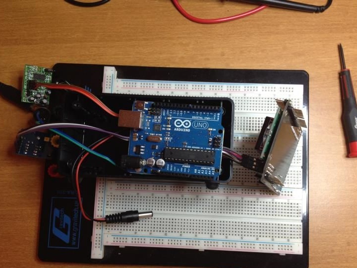
Step Five Installation in a box.
In this step, the structure is placed in a separate box.First of all, cables from the LCD shield are laid in the box. Arduino is secured with a screw on the lower right side of the case. To hold the microcontroller, one screw is enough, especially since the author uses a box in which stiffening ribs are located in place of the holes for the other two screws. Next, an LCD shield is installed on the Arduino, the cables of which envelope the board on the right side (seen in the photo below). The watch module is great for installation in the lower left corner, one screw is used to fasten it. This installation of components allows you to easily connect the 2.1 mm jack to the Arduino. The motion sensor is set so that it is possible to remove it, because it interferes with connecting the USB cable to the board.
Step Six Programming.
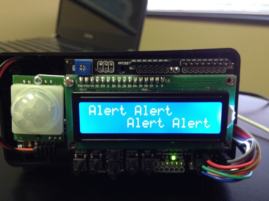
As indicated at the beginning of the article, the clock should not only display the time and date, but also a timer with alarms. There are 5 buttons on the shield that can be programmed. They will be used for various hours of operation. The buzzer will work when each button is pressed, and when the alarm is working, it will give out several signals.
Sketch for Arduino.
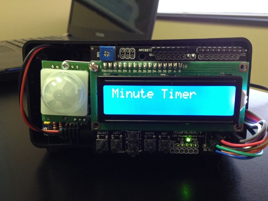
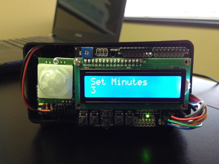
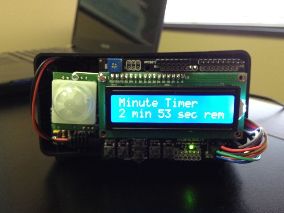
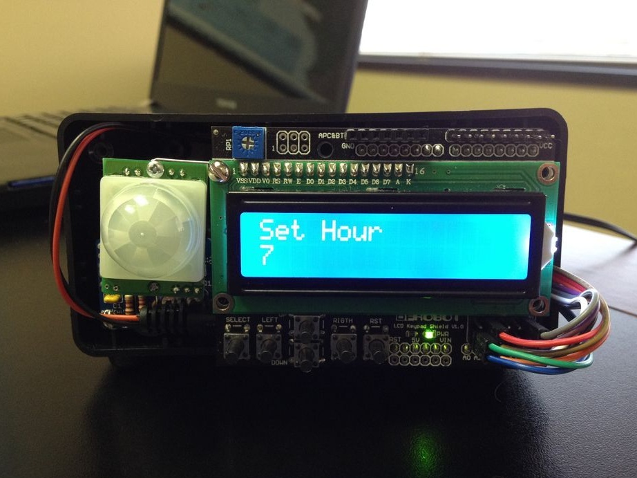
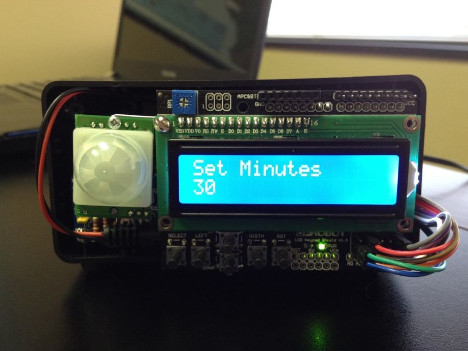
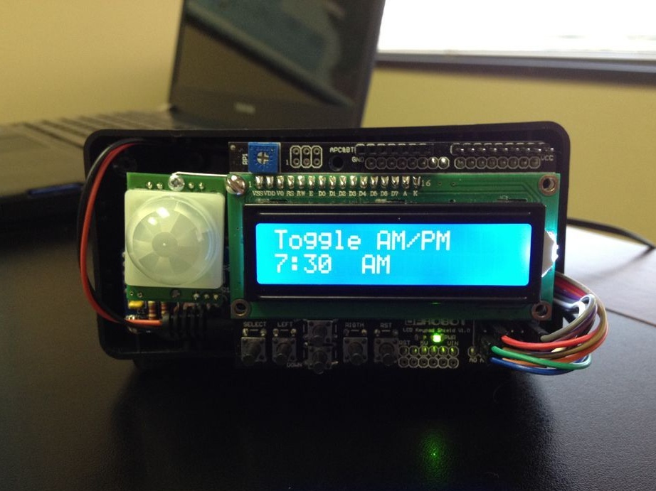
The author took the sketch from Adafruit as the basis, it was developed for a real-time clock. It uses the RTClib library. Further, the author added a piece of code for the LCD shield from DFRobot (button control option). And he added a piece of code from himself exclusively for this project. The final version of the code can be downloaded under the article. Below are photos with different watch modes.


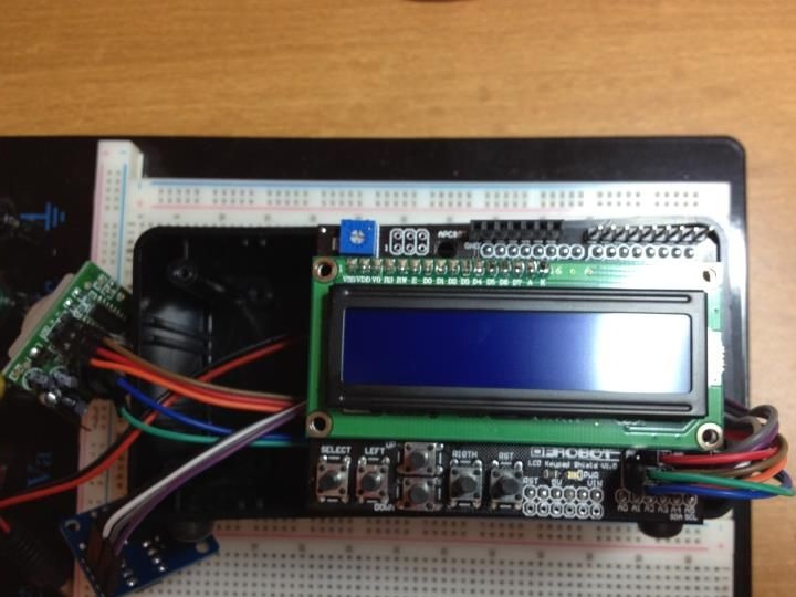
Seventh step. Button Functions.
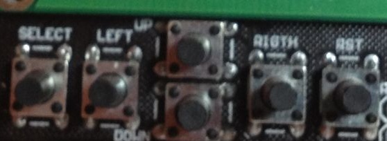
As you can see in the photo below, each button on the shield is signed, five of them were programmed as follows:
- The first button (SELECT) is the menu. The button displays the scrolling of available functions (timer, alarm).
- Second button (LEFT) - this button is responsible for selecting a function. An additional function of the button is increasing the value by 10 when hours and minutes are entered.
- The third and fourth buttons (UP, DOWN) - are used to increase and decrease the values of hours and minutes when setting the alarm and timer. Additional button function for switching the time of day AM and PM.
- The fifth button (RIGHT) is the enter button. Used to accept a value (configured timer time, hours).
- Sixth button (RST) - the button is used to restart the Arduino.