

The author based this project on a simpler version. homemade boats, and perfected it. Sensors are placed in the boat to avoid obstacles and to move into the light. How the controller in the boat is used Arduino, an ultrasonic sensor is installed in front, and light sensors are located on the sides. This simple boat does not crash into the walls, and is controlled by a flashlight.
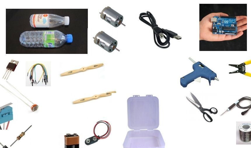
Materials and tools:
- Insulating tape / adhesive tape
- Thermoglue with hot glue
- DC motors 2 pcs
- Plastic bottles 2 pcs
- wires
- Small propellers 2 pcs
- Arduino, computer and USB cable
- Plastic box
- 9V battery and connector
- Power diodes (type 1N4004)
- Resistors
- Transistor MOSFET or TIP 120
- Two photocells and two buttons
- scissors
- Solder with a soldering iron
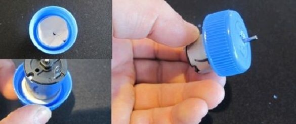
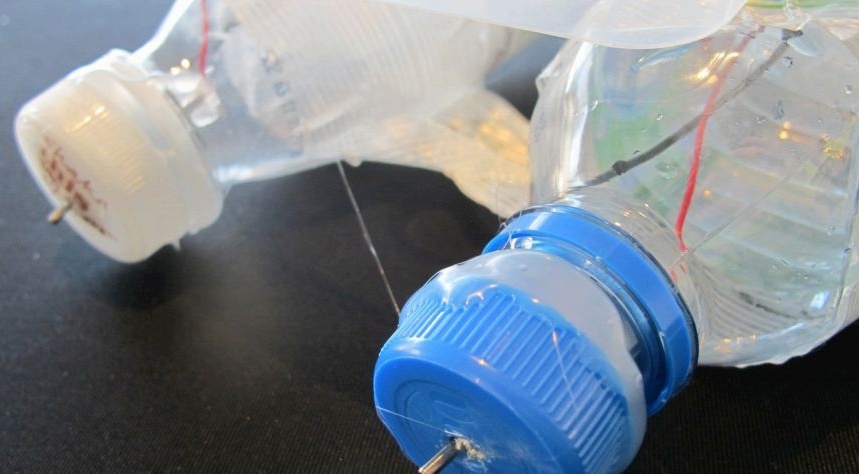
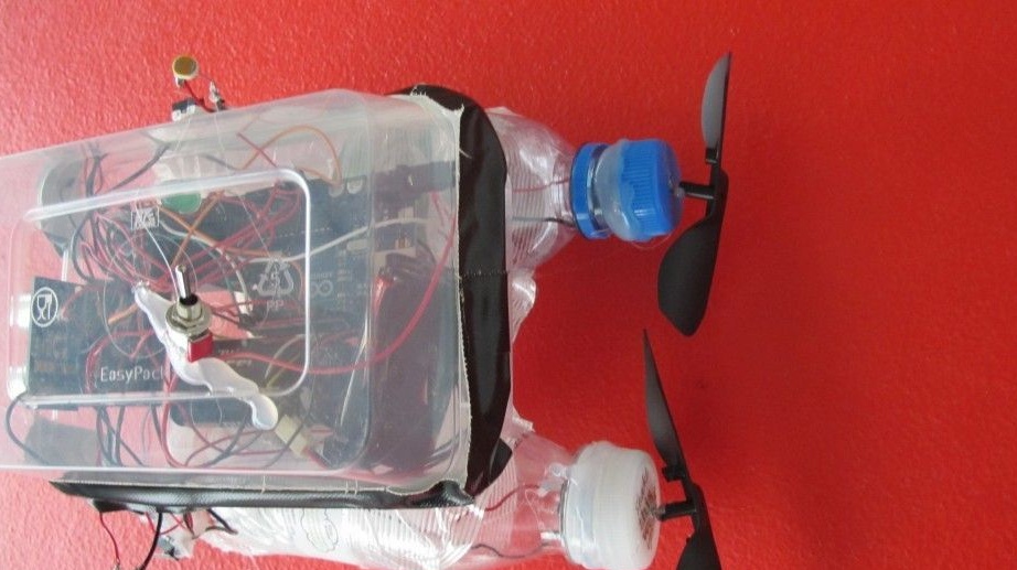
Step 1. Installing engines.
Lids are removed from the bottles and a hole is made in each of them. Inside the cover, the author squeezes hot glue without closing the holes. He placed the motor shaft in the hole and put it on the glue. After the glue dries, the shaft rotates freely. The same procedure occurs with the second cover.
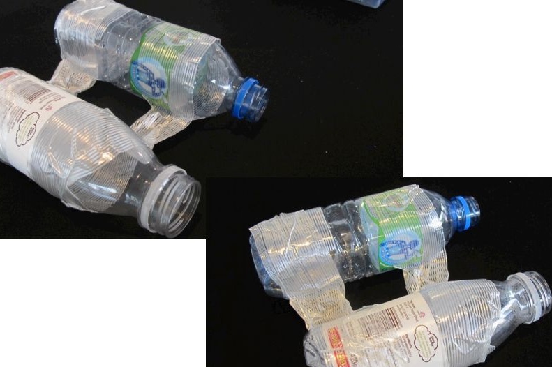
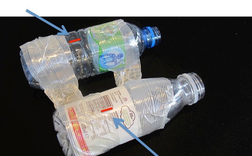
Step 2. Attaching the bottles.
The bottles were fastened together by the principle of a raft with the help of three strips of adhesive tape.
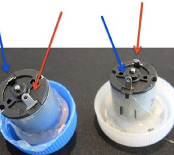
Step 3. Soldering to the engines.
Since the engines mounted in the plugs did not have wires, it was necessary to solder them, the length of the wires was about 25-30 cm.
Step 4. The cut in the bottles.
In order for the wires to fall into the hull of the boat, a small slot is made from their upper side.
Step 5. Securing the motors.
Further, the author twists the lids on the bottles, since they did not twist well; I had to use hot glue. Wires are pushed through the prepared holes on the bottles.
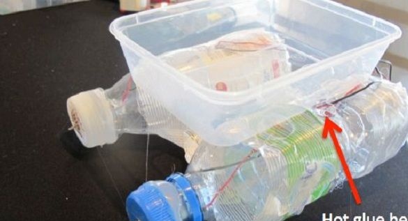
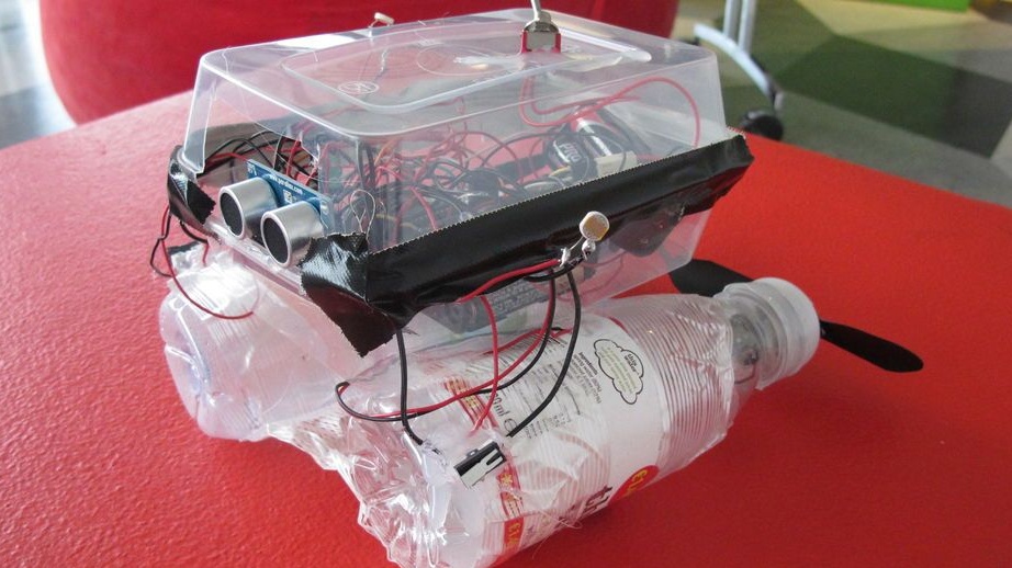
Step 6. Case.
A plastic box sticks to two bottles. In this capacitance for electronics, you can make holes for the wires, or hold the wires through the back of the box. The holes for the wires on the bottles are insulated with hot melt adhesive.
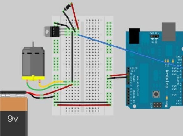
Step 7. Wiring diagram.
The circuit uses a TIP 120 transistor as a switch (you can use similar MOSFET or Darlington transistors). It is used to switch the load when consuming a large amount of current, since the Arduino does not have enough power for the motors. This circuit is assembled for the first and then for the second engine (another battery is not needed for the second engine).
Step 8. Sensors.
The ultrasonic sensor is great for the front of the boat, warns of obstacles on the way. Photocells act like antennas and are used to make the boat float into the light.The buttons on the sides are used as obstacle sensors. You can also modify the code and use other sensors, such as infrared.
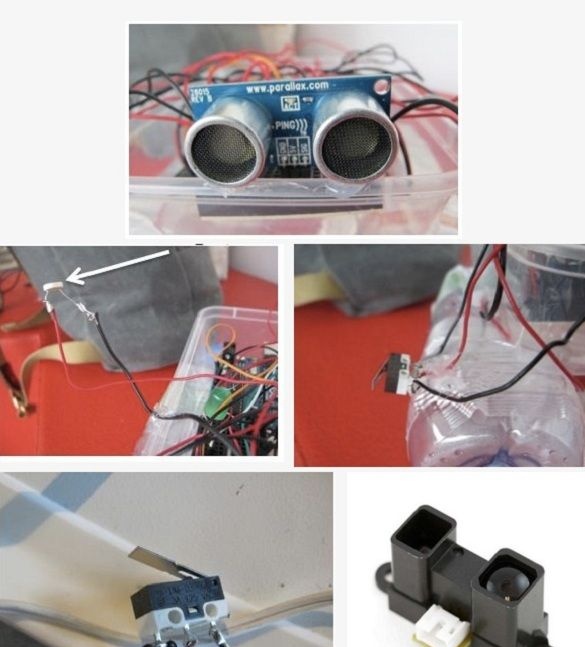
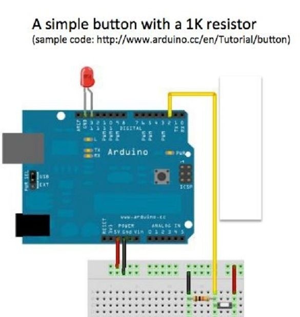
Step 9. Schemes for sensors.
The diagram shows the connection of a simple button and a 1K resistor. The scheme for both buttons is repeated, the buttons are placed on both sides of the boat. They will be responsible for changing the movement of the boat in a collision.
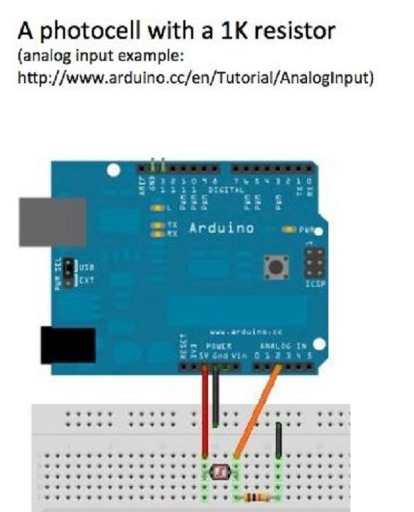
The following figure shows a circuit with a 1K resistor and photocell. The author performed it 2 times and placed the photocells on opposite sides of the boat.
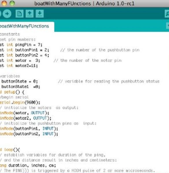
Step 10. Program code.
The author provided the opportunity to download its code for use, thereby providing basic functionality for those who will assemble such a boat. The code includes support for photocells, rangefinder and buttons. The boat will try to avoid obstacles in front of itself, and turns in the opposite direction when it encounters obstacles from the side. If there is no desire to use the entire set of sensors, but only some of them have a code for each separately. You can download all the codes under the article.
Step 11. Assembling the boat.
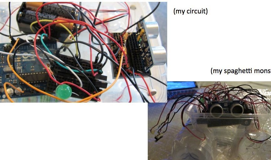
Assembled circuit, Arduino and batteries are boxed.
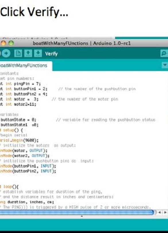
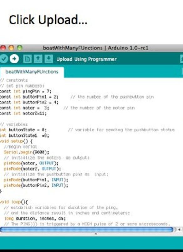
Step 12. Download the sketch.
Next, the Arduino IDE opens, selecting the correct file and port, after which the author compiled and uploaded the code to the controller.

Step 13. Water resistant and test.
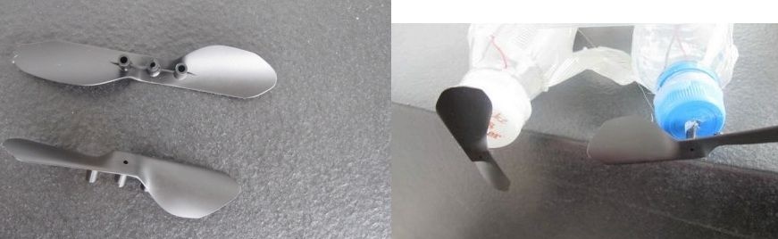
The author additionally isolated all potential places of water ingress with hot glue. Also insulated all wires from short circuit. The container with Arduino is covered with the same box and sealed with electrical tape. Propellers are attached to the motors. Here the boat is ready, now you can start testing on the water.
Video with a preliminary test of the boat: