

Having received a couple of boards Arduino, and various radio components to get acquainted with microcontrollers, the author decided to do something interesting and at the same time useful. Having in stock a large number of LEDs, the idea came up to create a binary clock.
On the electronics side, a binary clock is not particularly complicated, but the author complicated the task and decided not to save buttons and LEDs. Initially, the project was to use 22 LEDs, 6 buttons, and one tweeter. It was also an idea to assemble a watch on the Arduino Mega due to a larger number of pins, but the shift registers 74HC595 turned out to be a salvation.
Materials:
- Arduino Uno
- 2 full-size breadboards
- LEDs red 7 pcs
- Green LEDs 7 pcs
- Blue LEDs 6 pcs
- 2 yellow and white LEDs
- Resistors 220 ohms 25 pcs
- Piezo buzzer 1 pc
- 6 buttons tact buttons
- Shift output registers 74HC595 in DIP-16 package 3 pcs
- Connecting wires 90 pcs
- Real-time clock module based on the DS1307 RTC chip
How everything will work.
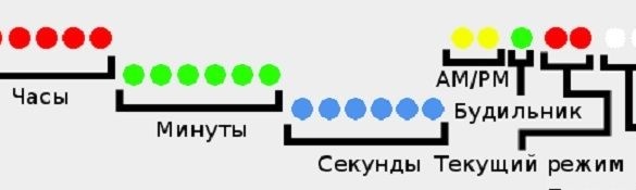
There are about 10 types of binary clocks. Some show time in binary decimal (BCD) format, others as binary numbers. Since the author does not particularly like the BCD-watch, he decided to make his pure binary. Some people find it harder to read, but the difference is not big, because translating numbers from binary to decimal is easy. Also a prerequisite for the creator of the watch was an indication of the seconds on the watch.
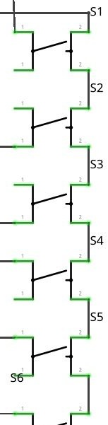
In addition, the watch has 6 buttons:
Set - is responsible for the clock / alarm setting mode and saving the parameter in the setting mode.
Mode - responsible for switching between the clock, alarm and timer modes.
Up - in the clock / alarm / timer setting, increases the parameter by one. In the alarm clock and timer, it is responsible for activating and deactivating the selected mode. When a signal is triggered, it will turn off the alarm / timer signal.
Down - in the clock / alarm / timer setting, it will decrease the parameter by one. The timer will pause it without resetting the countdown. When the alarm goes off, it will transfer the signal for 5 minutes.
24/12 - change the time format.
Dim - responsible for turning on and off the LEDs (when the LEDs are off, the remaining buttons stop working).
LED positioning diagram:
Component Connection
The author will connect all the LEDs in series and with a resistor. The resistor is soldered to one of the terminals of the LEDs, it does not matter which one. LEDs will be connected through shift registers, this chip has 16 contacts.This number of pins allows you to use a large number of pins, taking only 3 pins on the Arduino.
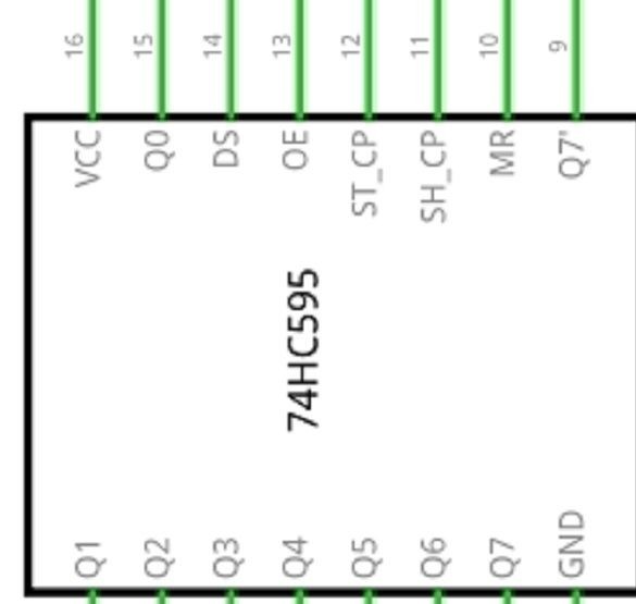
Shift Register Pinout 74HC595:
Q0-Q7 are the findings of the register to which the LEDs will be connected.
Vcc - a 5V power supply pin will be applied to it.
GND - ground connected to GND on Arduino.
OE - the pin is responsible for the inverted activation of the pins, but it will not be used, it is simply shorted to ground.
MR is an inverted register clearing, it does not need to be controlled, therefore it will be connected to a 5V power supply.
ST_CP - pin is responsible for updating the status of the register. When recording the state, it is necessary to apply LOW to it, after recording - HIGH, to update the status of the outputs. It needs to be connected to a pin on the Arduino. You can connect this pin in three registers in parallel.
SH_CP - pin, responsible for the shift by 1 bit of the register. It needs to be connected to a pin on the Arduino. They are connected on microcircuits also in parallel.
DS - data is being sent to this pin, it is connected to the pin on the Arduino.
Q7 '- this pin is used for cascade connection with other registers 74HC595.
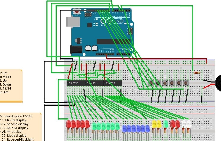
Wiring diagram:
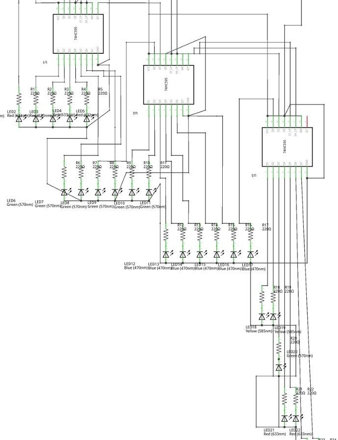
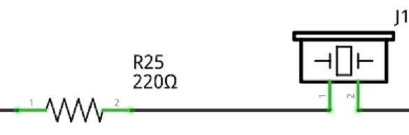
The piezo buzzer will be connected to the third Arduino pin in series with the resistor. Before including the tweeter in the circuit, the author looked at which pins support PWM, since this is mandatory for her. On the Arduino Uno, PWM supports 3, 5, 6, 9, 10, and 11 pins.
The buttons are connected using resistors built into the Arduino, with one side of the buttons connected to the ground and the other to the Arduino pins.
So, the final design looks:
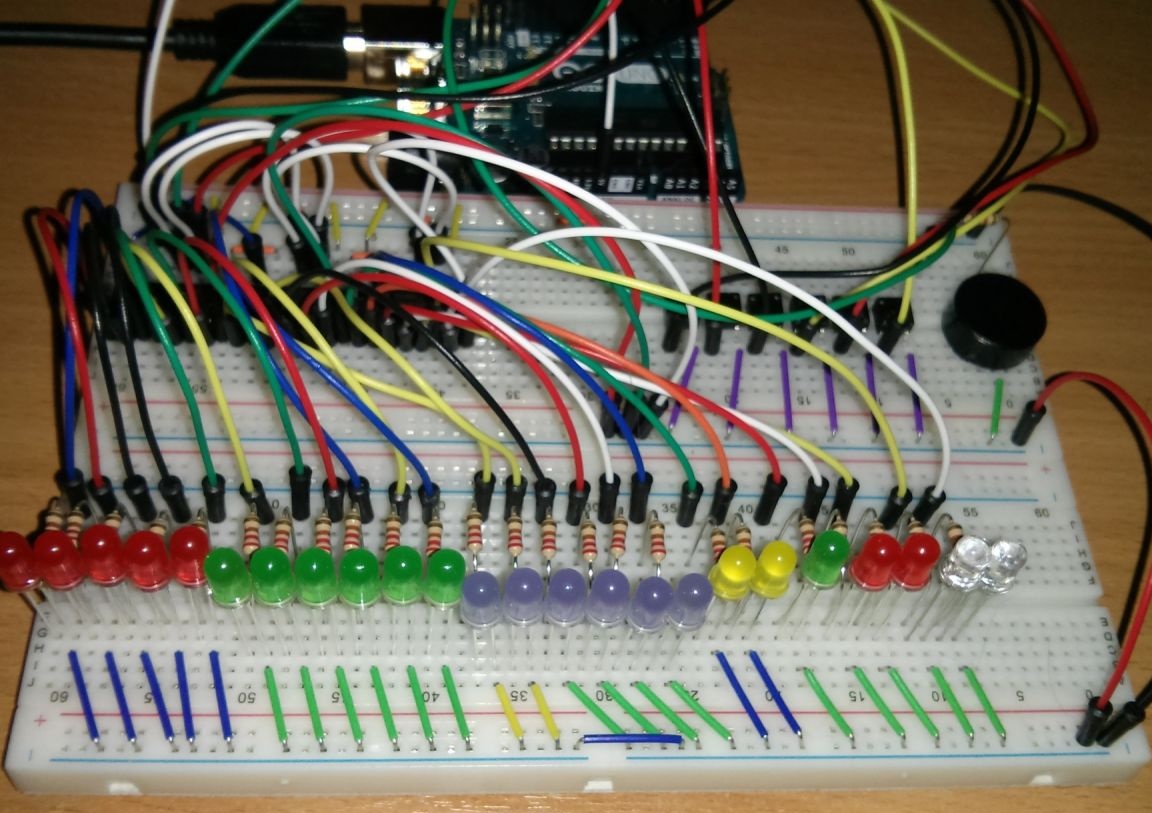
Build on Breadboard
After acquiring additional details, the author began assembling the project on a breadboard according to the schemes. Appearance was about to be expected, because the Breadboard limits the freedom in the placement of components, and the protruding wires did not create an aesthetic pleasure. But the breadboard after all is intended for breadboard models, but not for finished devices.
Program code.
Having a savvy in programming, the author decided to write code on his own, without using other people's developments. The first step was to write a subroutine, it is responsible for blinking all the diodes and giving the piezo signal when turned on. This function helps to verify the integrity of the circuit, similar to that implemented on many devices.
The sketch came out quite large, then you can consider its main features.
LED work.
Since the LEDs are accessed through the shift register, first of all, it was necessary to implement more routines for the LEDs. For easier operation with diodes, a number of additional functions have been implemented. Various effects of animation of diodes are implemented. When the clock is not set, the diodes responsible for the hours and minutes will begin to flash (as a normal clock flashes when not set). The LEDs responsible for seconds also have their own animation, the diode can run left and right in the alarm mode, or in the clock setting mode.
Main loop.
The program is configured to work as follows: the clock displays information depending on the current state, and change its state depending on the use of buttons and events. It all looks like a considerable amount of nested conditions. The state of the diodes is updated every time after checking the status of timers and buttons with a call to their handler.
Also, the author did a great job for the correct operation of the input buttons and timers. The source code of the sketch can be downloaded under the article.

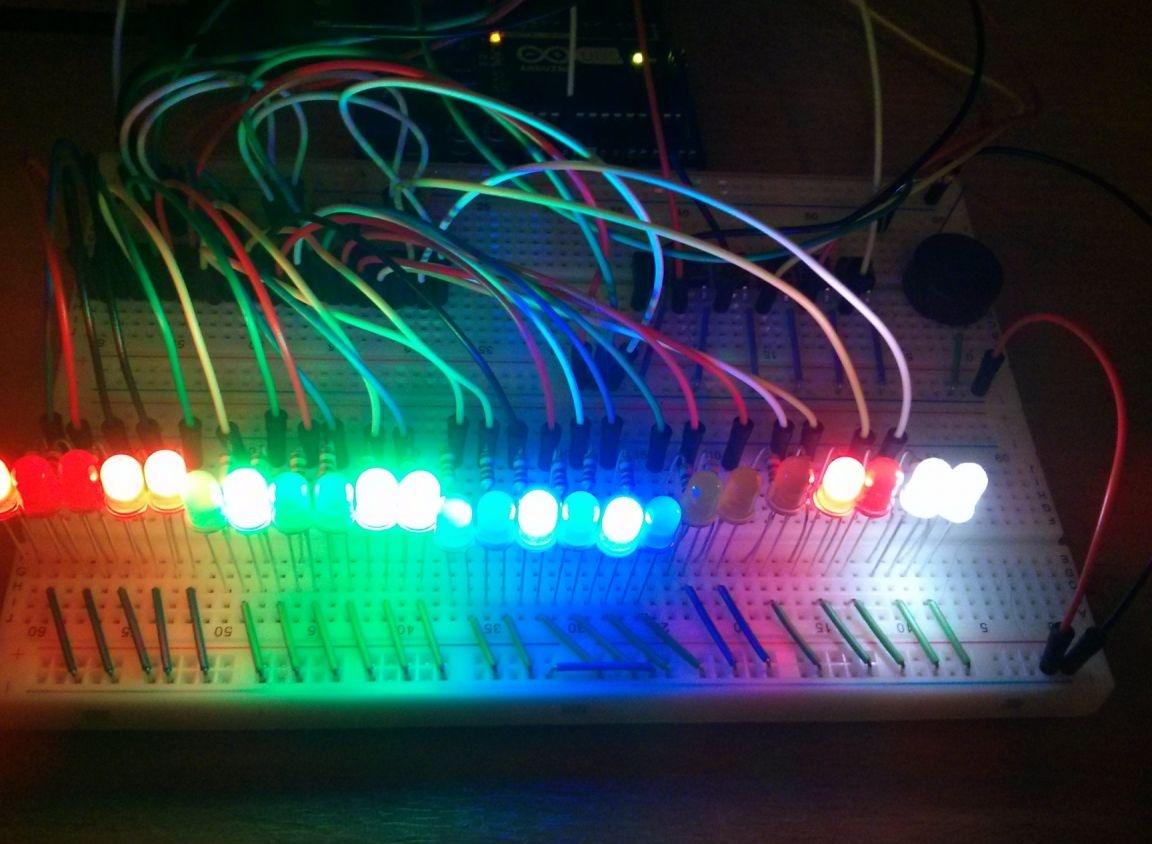
Launch layout
After turning on the project, at first glance, the device worked correctly and stably. But the author found a flaw, the clock was behind by one second per hour, for a long time it would be a big error.
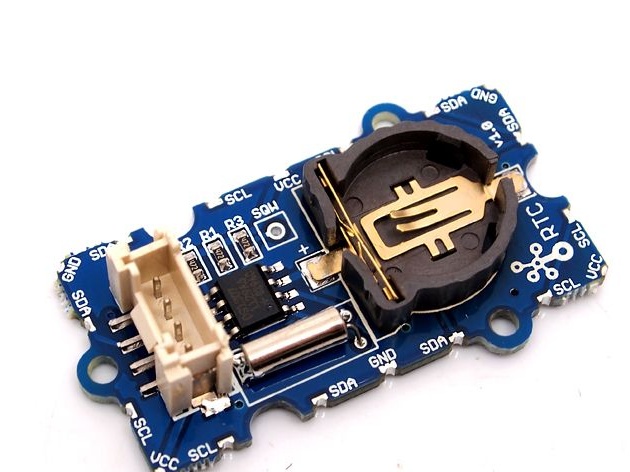
Having studied this problem, it was found that the original Arduino Uno uses a ceramic resonator, and it lacks accuracy for measuring time in long periods. The most rational solution was to buy a real-time clock, plus because of this module, the time on the clock will not go astray when turned off. The author purchased the Grove RTC module from Seeed Studio. It is a finished board with a clock chip. The author connected the pins of the SDA and SCL module to the Arduino on the pins of A4 and A5, GND to ground. Since the 5V power is occupied by the clock board, there was nowhere to connect the module. The author decided to power the module from one of the digital pins, which will be constantly energized.Also, the author needed to modify the source code and add a library of real-time clocks.
Watch assembly
Having completed a long work on the code, it's time to give the device a complete look and transfer it from the breadboard to the printed circuit board. First of all, it was necessary to make the wiring for the board. Fritzing was used for this, since the author already had an idea of the appearance of the watch, and he built a device diagram. The author also manually traced the board, it took a lot of time.
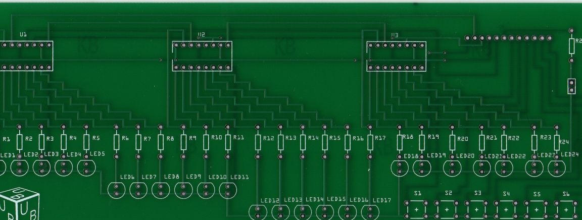
Project for the production of printed circuit boards:
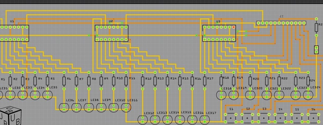
PCB manufacturing was ordered in China. Seeed Studio has a Fusion PCB board service. Through Fritzing, the file was exported to the Extended Gerber format, many board manufacturers work with it. Two weeks later, the author received the long-awaited fee in the mail.
It only remained to solder already a little dusty parts onto the board. The finished result after soldering looked much better than the layout on the Breadboard.
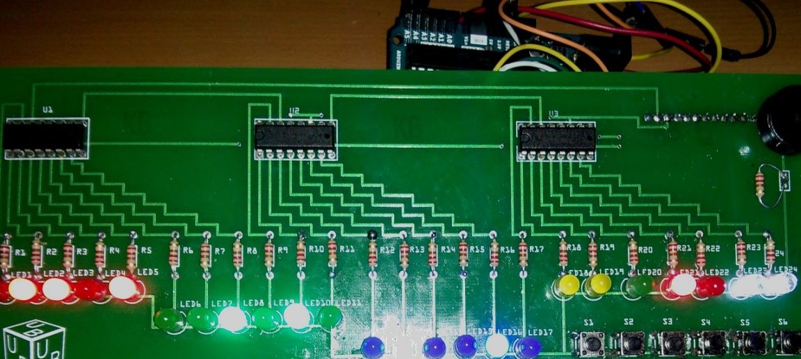
The author of the project worked hard for a long time and got what he wanted - a unique binary clock with a timer and an alarm clock. Using the battery compartment, the watch can be placed anywhere. Arduino met expectations and completely coped with the task.