
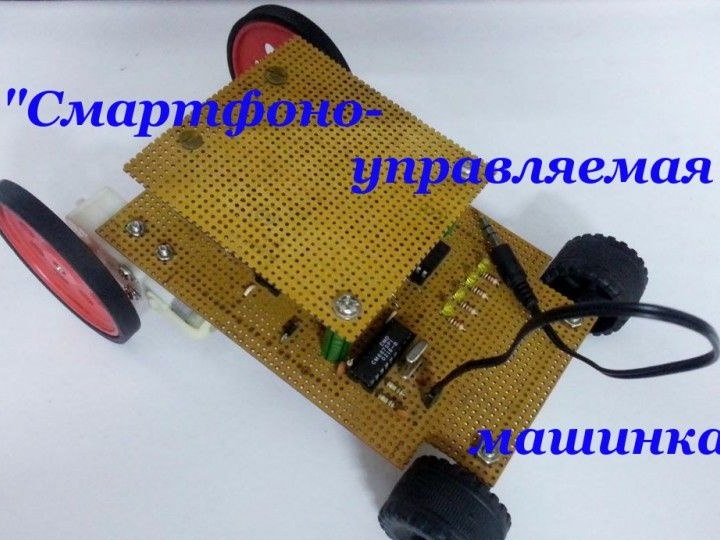
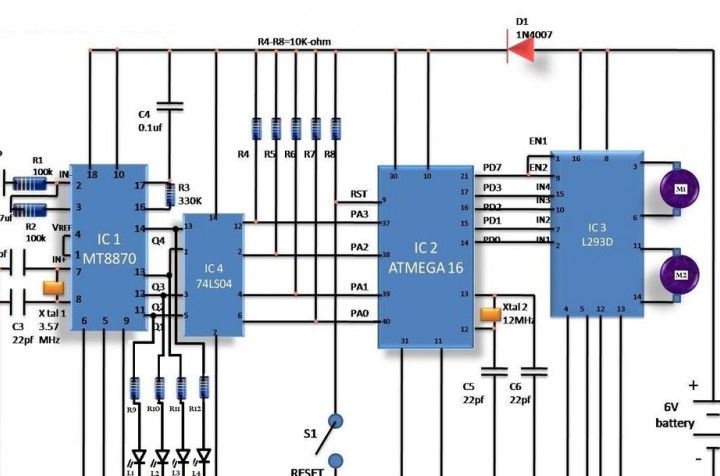
The decoder will convert the tone into a binary code equivalent to that signal. Further, this binary signal will go to the controller, but the controller itself will control the drivers of the motors, which will move the machine in a given direction.
According to the author, the main advantage of this homemade is that thanks to this approach it is possible to overcome the limit of the range. This problem can be encountered when working on radio frequencies.
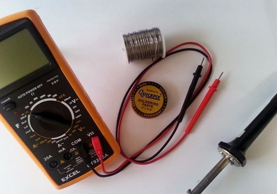
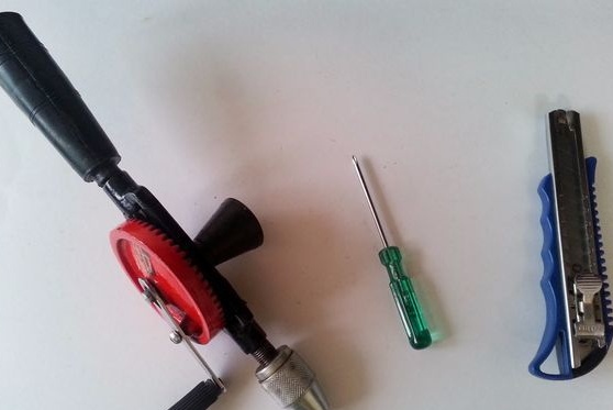
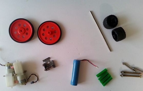
Tools and materials for assembly:
- soldering iron with solder and flux;
- electric drill (also suitable manual);
- knife;
- screwdriver;
- multimeter;
- printed circuit board;
- rectifier diode 1N4007;
- voltage regulator 7805v;
- motor driver L293D;
- MT8870 DTMF decoder;
- chip 74LS04 NOT gate;
- AVR microcontroller ATmega16;
- old headphones;
- quartz resonator XTAL1 - 3.57MHz;
- push switch;
- quartz resonator XTAL2 - 12 MHz;
- pin connectors "male", "mother";
- two DC motors 6V, 50 rpm with brackets;
- four wheels;
- battery type 6V, 4.5 A / h;
- five LEDs of any color (3 mm);
- a straw or case from a plastic handle;
- nuts with 2-inch bolts (4 pieces).
Resistors: 100 kOhm (2 pcs.), 330 kOhm (1 pc.), 10 kOhm (5 pc.), 100 ohm (4 pc.).
Capacitors: ceramic 0.1μF (1 pc.), Ceramic 22p (4 pcs.), Electrolytic 10uF, 100uF (2 pcs.).
Machine assembly process:
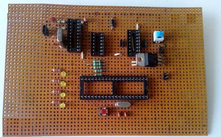
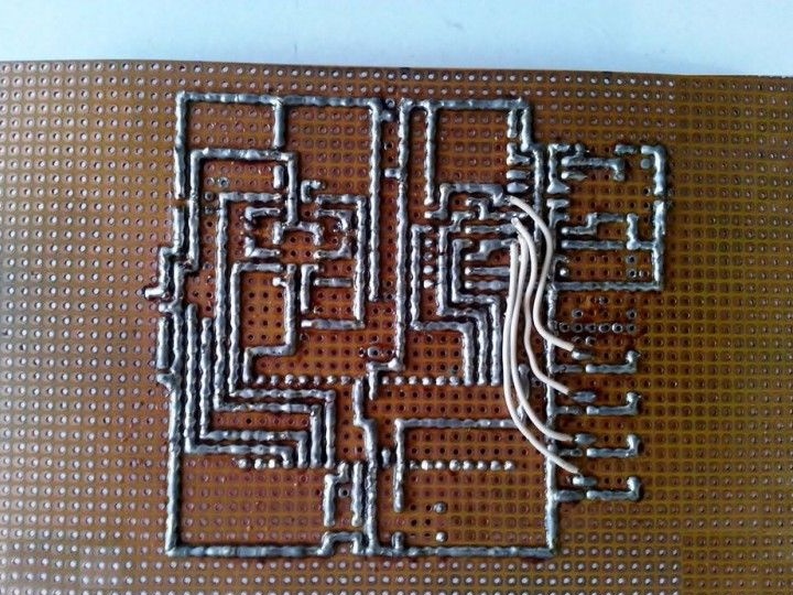
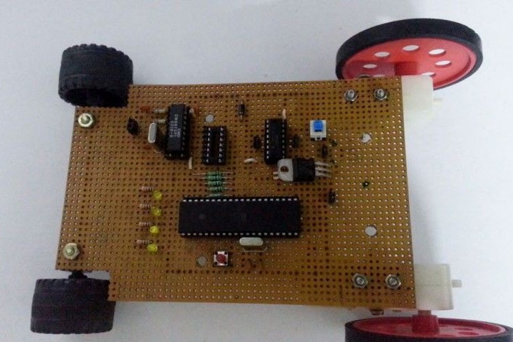
Step 1. Solder the circuit
Assembly begins with the soldering of the ATmega16 microcontroller, as well as other components, as indicated in the diagram. It is necessary to solder carefully and carefully, without departing from the circuit.
The author for the circuit made an additional regulated 5V power supply, the voltage regulator 7805 is used. If the battery rating is below the operating range of the controller, then you do not need to use the regulator. It is necessary only if the operating voltage of the battery is more than 6V.
Alternatively, you can use a breadboard instead of soldering.
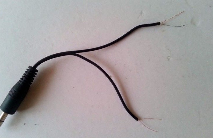
Step 2. Making the connecting cable
In order to make the connecting cable you will need old headphones, you need to cut off the audio plug from them with a wire margin of about 30 cm. After this, the wiring must be thoroughly stripped. The result should be two pairs of wires, most often it is red-golden and blue-golden, but the colors can be different depending on the manufacturer.
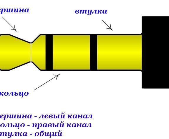
Golden wiring can be twisted together and insulated, or even cut off. Only two wires are needed for the circuit, these are red and blue. One wire is connected to the top of the plug, and dredge to the ring. After stripping the wiring, you need to solder to the two-pin male connector. In order to insulate the wiring well, you can use a heat shrink tube.
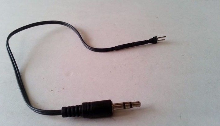
After the cable is made, you need to take a multimeter and decide which contact is connected to what. Directly, the wire itself will be connected to the board using a pin connector, but to a smartphone using an audio plug.
Step 3. Homemade software
The microcontroller code was created in C, it was compiled in AVR Studio. The code itself is very simple and uses only the basic functions of the controller. The firmware attached to the article must be written to the controller using the AVR editor.
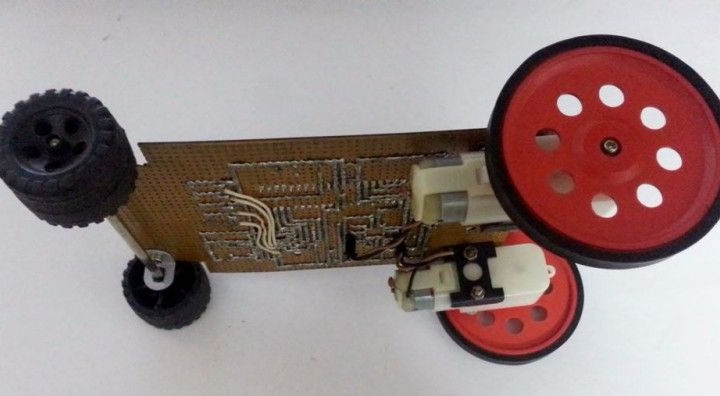
Step 4. Installing peripheral parts
In order to install the motors in the corners of the back of the board, you need to drill holes. On the front side there will be an axis, it can be a metal spoke or a thin pencil, then wheels are put on it. At the same stage, using a previously made cable, you can connect a smartphone to the typewriter. When connected, the smartphone must be switched to automatic answer mode.
After that, you can connect the battery and turn on homemade. If everything is done correctly, four LEDs should light up.
Step 5. Learning to drive a car
To start controlling the machine on a smartphone, you need to make a call. As already mentioned, IVRS technology is used here, that is, when a certain button is pressed, a certain tone signal is sent to the smartphone.
Button 8 means backward movement
Button 4 means move left
Button 5 is a stop
Button 6 is a right turn
Button 2 - Forward
Step 6. Final assembly phase
To make homemade work more beautiful, the machine can make a roof. A smartphone will also be installed on it. It is made from a piece of a printed circuit board, in the corners of which you need to drill holes. The roof is fastened with four bolts, four ducts of the required height are cut under them.
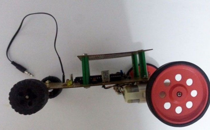
That's all, now the homemade product is ready. You can start the test.
[media = https: //youtu.be/loSME1w22UQ]