

The article shows the creation of a robot that travels along lines and can go through labyrinths, after studying the labyrinth, it can go through it in the shortest way. The author for a long time created this project, luck overtook him the third time.
Demonstration of the machine:
Materials and tools:
- Arduino RBBB
- Micromotors 2 pcs
- Brackets for 2 pcs engines
- Wheels 2 pcs
- ball wheel
- Analog reflection sensor
- Nuts with bolts of 2 pcs.
- engine driver
- Battery holder 4 pcs AAA
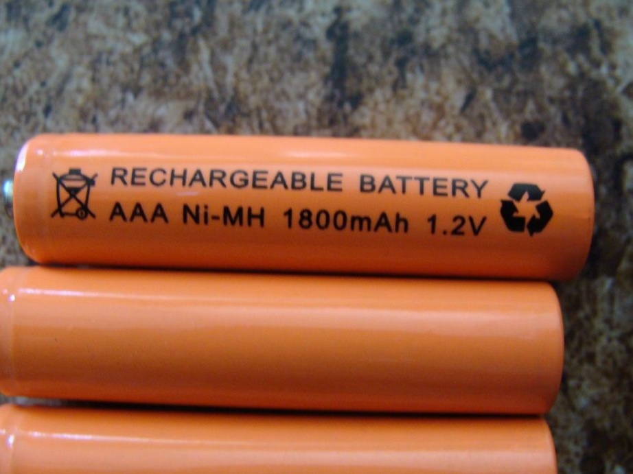
- Batteries (rechargeable batteries) AAA 4 pcs
- Case
- Nuts, bolts, washers
- connecting wires
- solder
- pliers
- soldering iron
- screwdriver
Step one. Theory.
The author needed robot, which itself will find a way out of the maze, after which it will be able to optimize the return trip. When creating machines for mazes, they were guided by the left-hand method. To make it clearer, you should imagine that you were in a maze and always keep your left hand on the wall. After passing a certain path, this will help you out of the maze if it is not closed. The robot can only work with open mazes.
The principles of the left-hand method are quite simple:
- If you can turn left, turn left.
- If it is possible to move straight, move straight.
- If you can turn right, turn right.
- If you are at a dead end, turn 180 degrees.
Also, the robot needs to make decisions at the intersection, but if it does not turn off at the turn, then it will go straight. To build a better return route, each decision is written to memory.
L = left turn
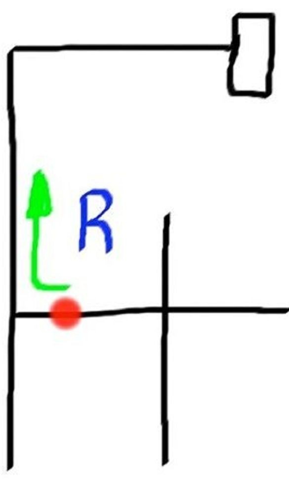
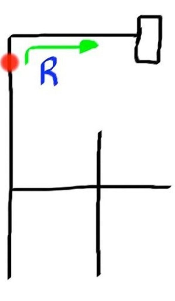
R = right turn
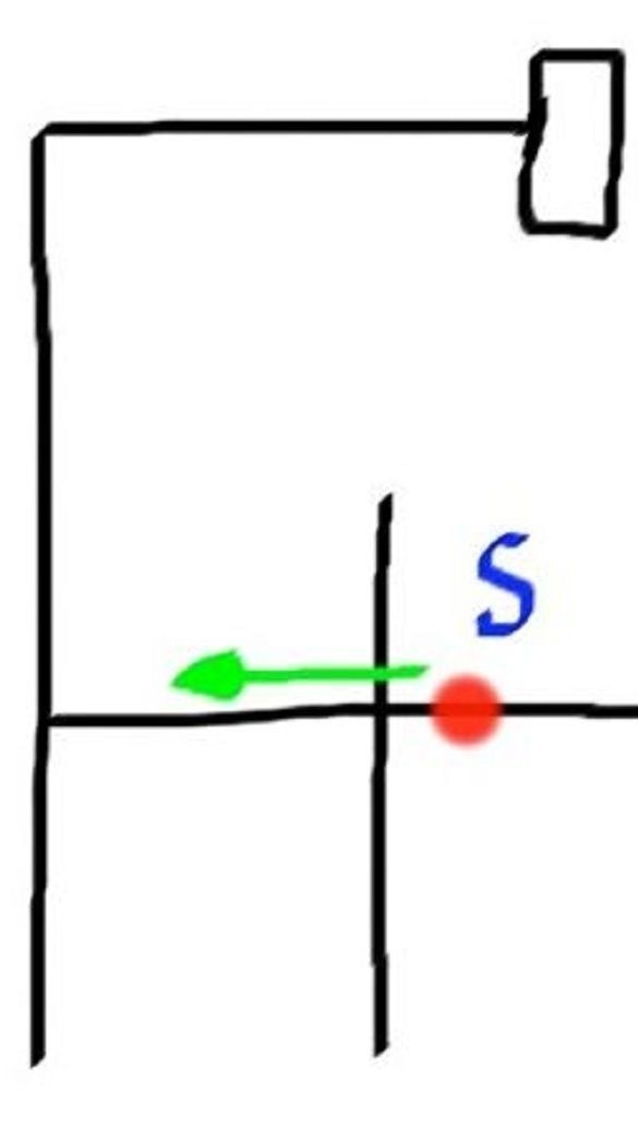
S = skip a turn
B = rotate 180 degrees
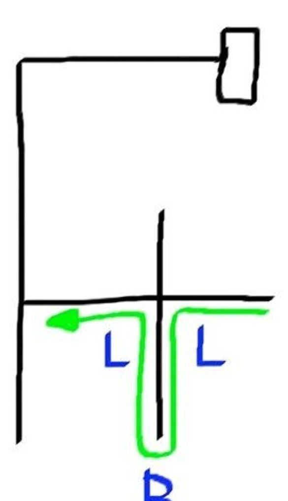
This method is shown below in action using a simple maze as an example. The robot covered the distance with LBLLBSR commands.
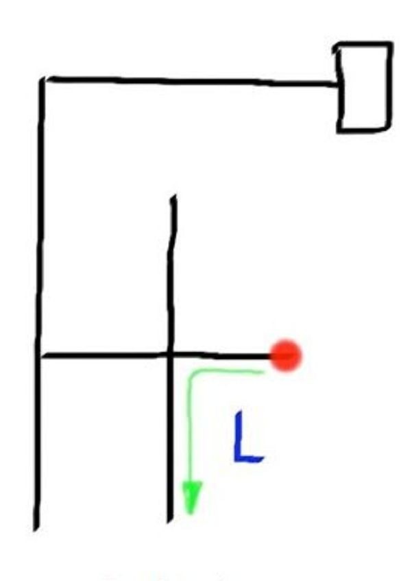
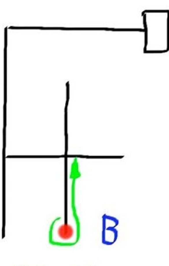
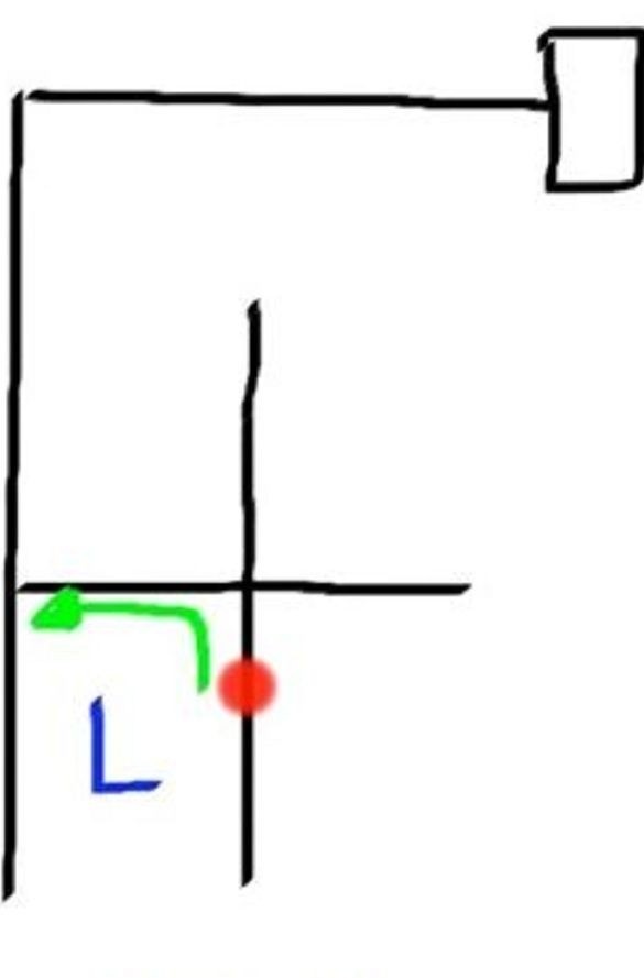
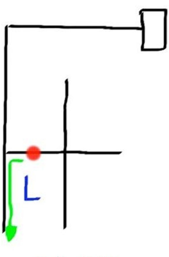
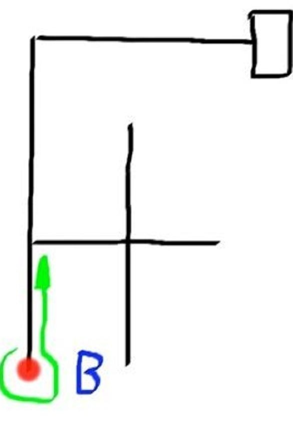
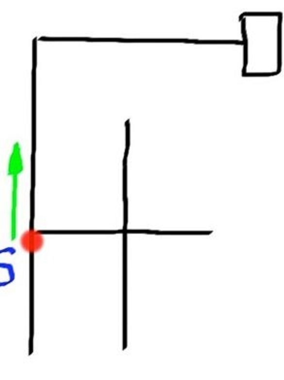
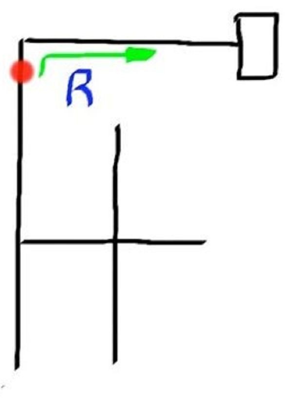
The path came out quite a long way; it needs to be turned into an optimal SRR. To do this, it is determined where the robot turned the wrong way. Everywhere where the “B” command is used, the path will be incorrect, since the robot was at an impasse, so “B” should be replaced with something else. The first wrong move was LBL, the robot turned and turned around, while it was just necessary to follow directly LBL = S. Thus, the ideal path LBL = S, LBS = R is built. Based on such replacements, the robot builds an ideal short path for itself.
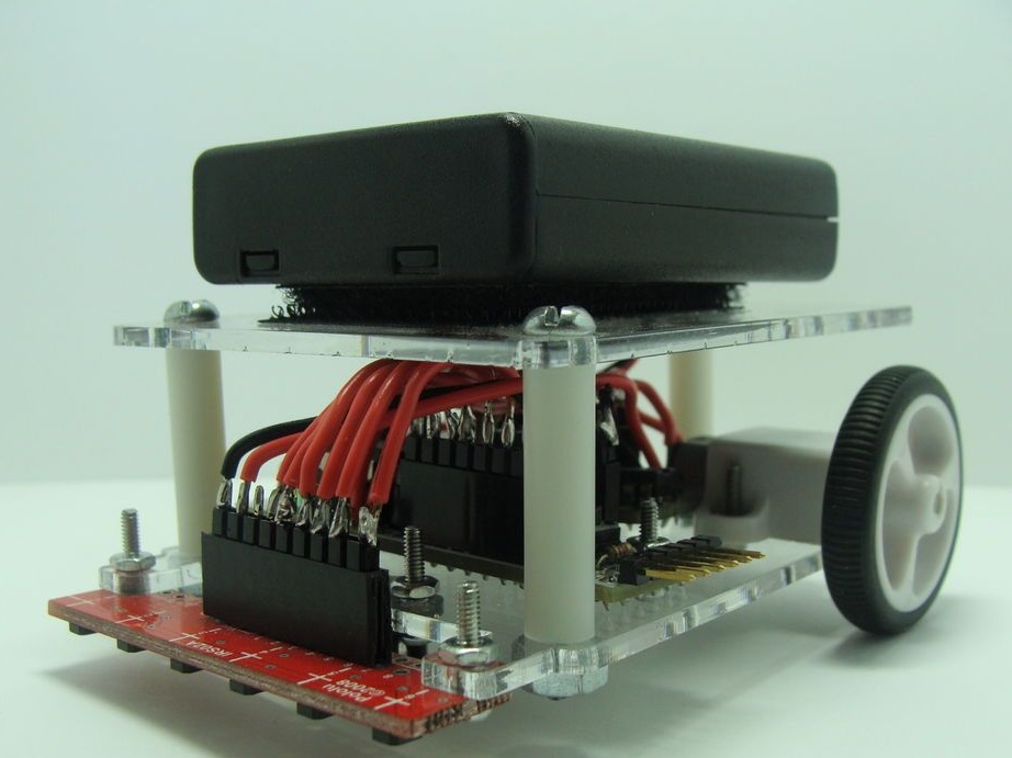
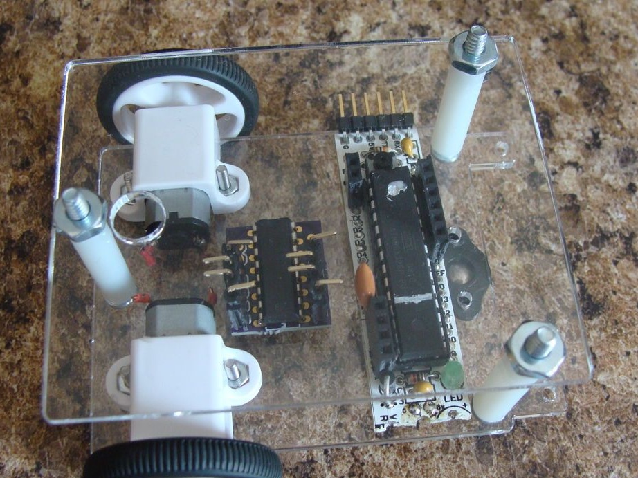
Step Two The chassis of the robot.
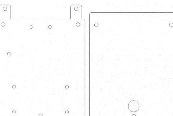
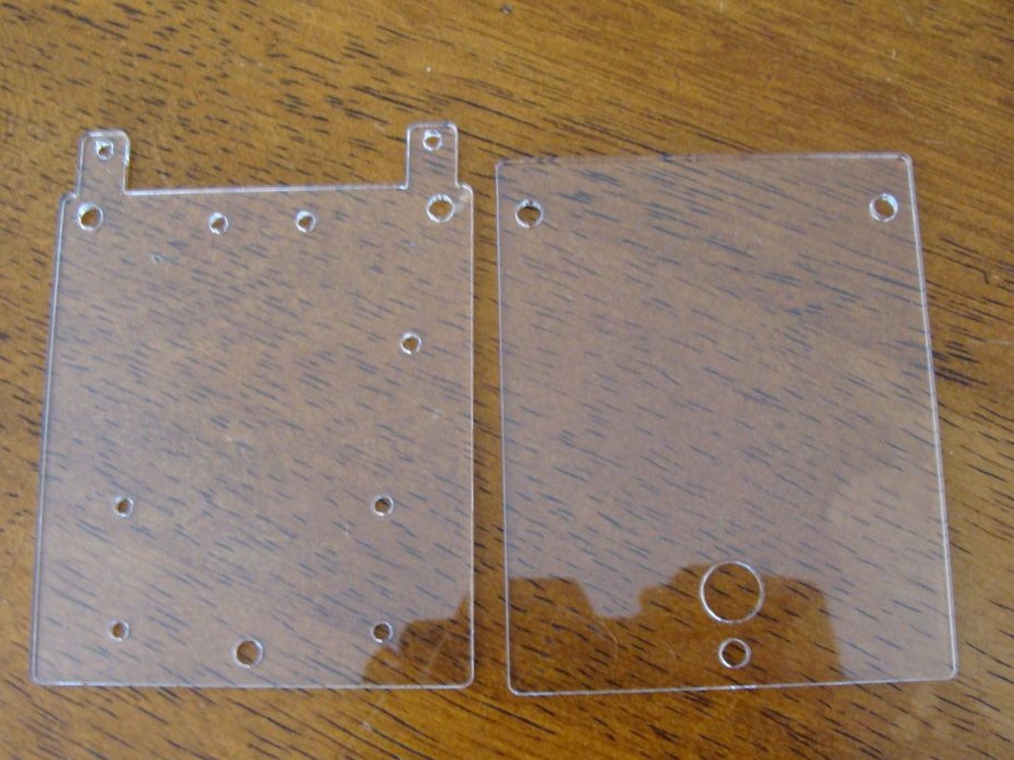
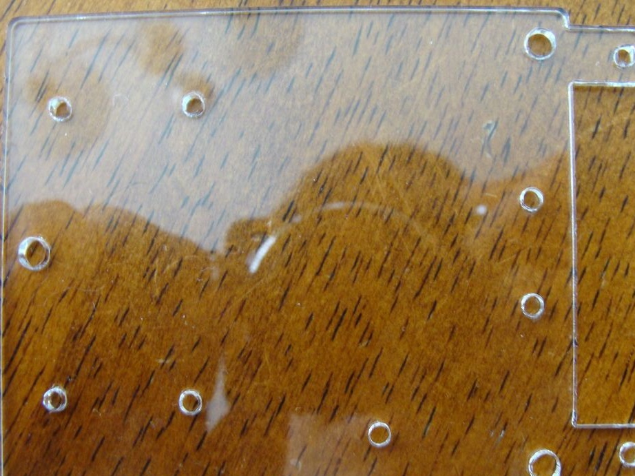
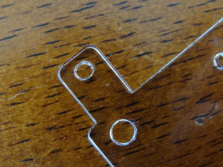
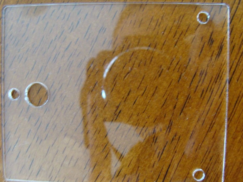
Acrylic with a thickness of 0.8 mm became the basis for the robot chassis; cutting was carried out by a laser according to the drawing. In the archive under the article there will be a drawing file from AutoCAD. It was not necessary to use such material, but the author took what was available.
In the lower part, holes are made for mounting motors, boards, wheels and sensors. The upper part has a large hole for wires.
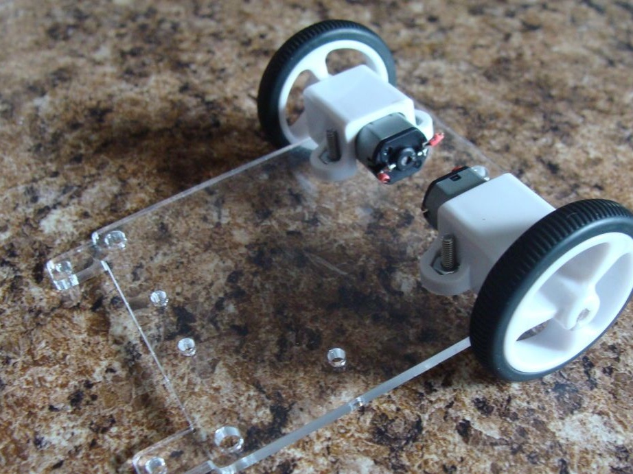
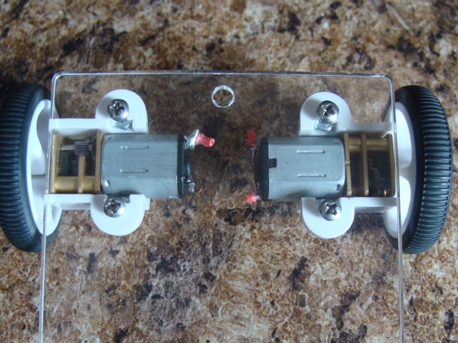
Step Three Installation of wheels.
The author attached both engines with bolts. Further, they simply put wheels on their axle, aligning the shaft with the hole in the wheel.
The fourth step. Arduino
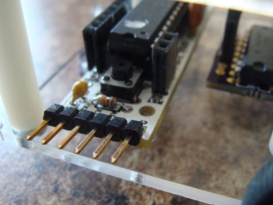
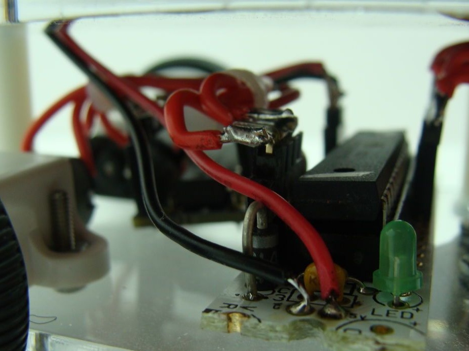
At this point, the author first followed the assembly instructions for the Arduino RBBB. Further, he cut off part of the board to reduce its size. The power connector and stabilizer were cut off with scissors for metal. After that, a 9-pin connector was soldered to the left side of the board for contacts from 5V to A0 to connect a sensor to it. A 4-pin connector was soldered to the right side of the board for contacts from D5 to D8, and a motor controller will be connected to it. To supply power, the 2-pin connector was soldered to 5V and GND.
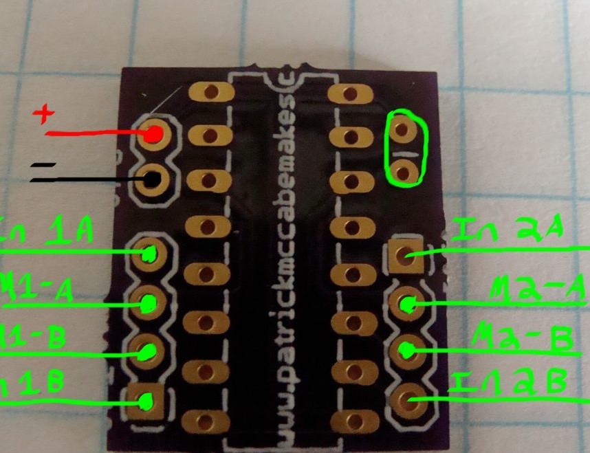
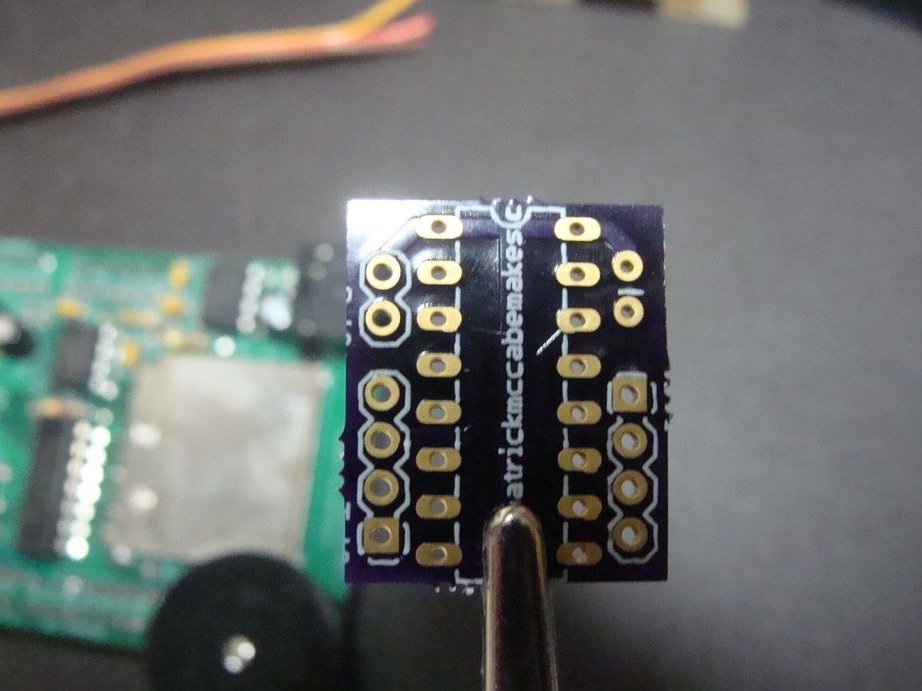
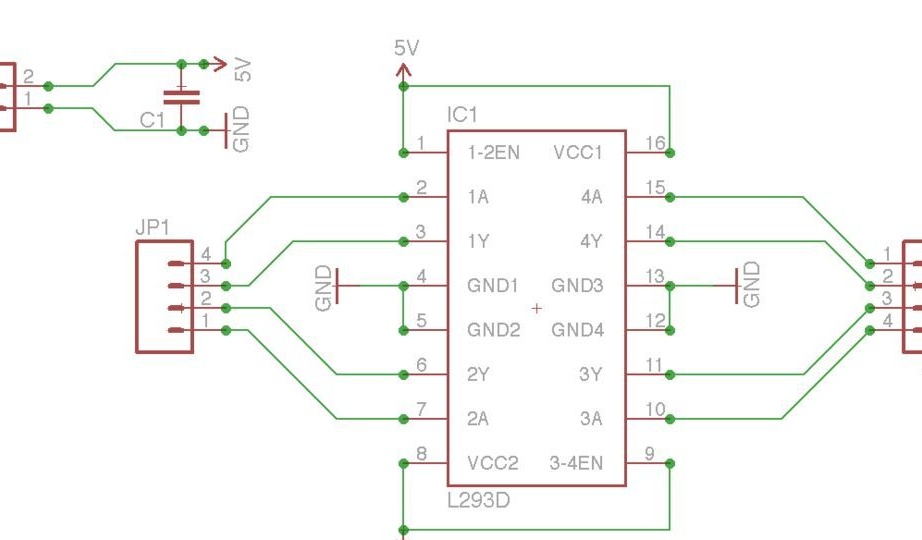
Step Five Motor controller.
The author himself developed a printed circuit board for this step, the circuit in the Eagle format is attached in the archive under the article. The first motor was connected to pins M1-A and M1-B, the second to M2 and M2-B. The first input of the first In 1A motor was connected to the 7th pin of the Arduino. In 1B was connected to pin 6 of the Arduino. To the first input of the second motor, In 2A is connected to the 5th pin of Arduino. Pin In 2B connects to pin 8 of the Arduino. Power and ground are connected to Arduino power and ground.
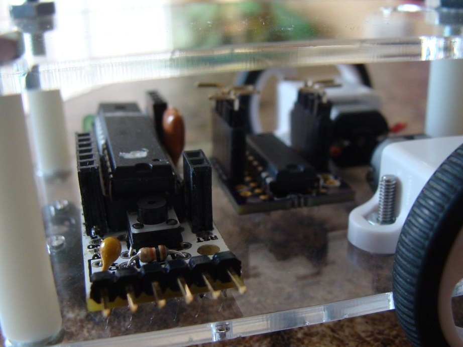
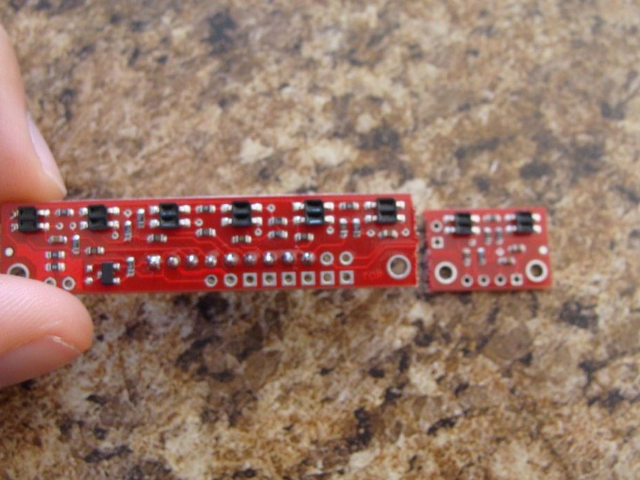
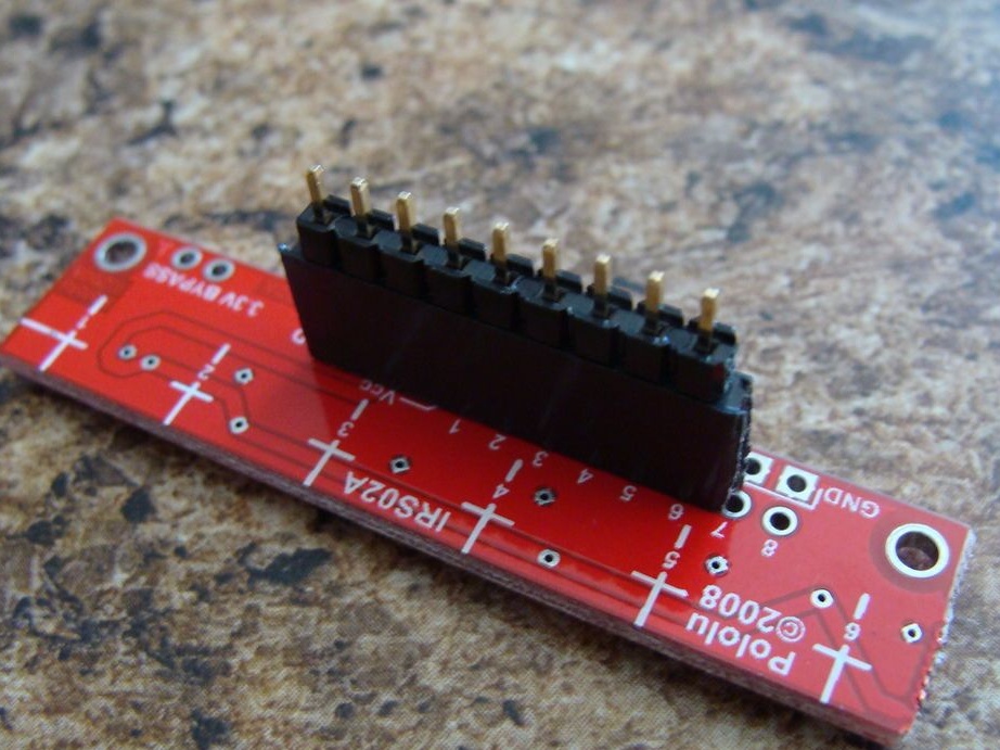
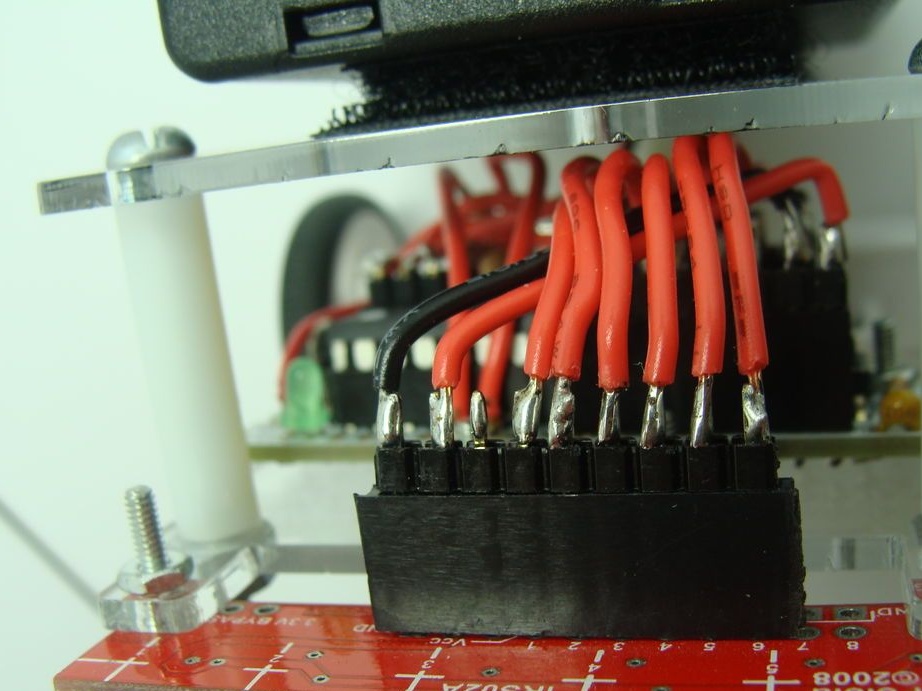
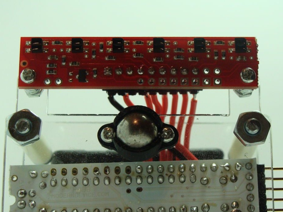
Step Six Sensors
This element is sold in the form of a board of sensors, initially there are eight of them, the two extreme ones were deleted by the author. A 9-pin connector was soldered to the board, a wire leading to the Arduino will be connected to them. The sensor detects a white and black part of the maze using reflection from the surface.
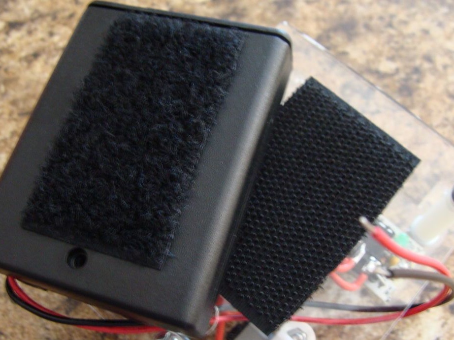
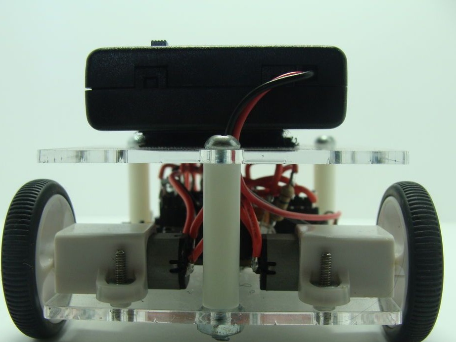
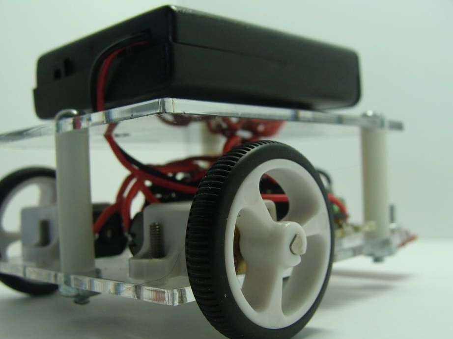
Seventh step. Top part.
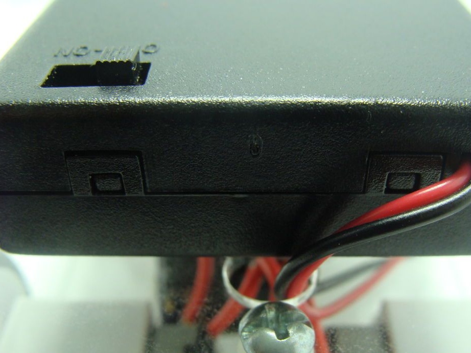
The chassis with the top of the robot connected by bolts and racks. The battery was fastened on the top with Velcro. Wires from him were laid through the prepared hole. When attaching, the author decided not to use screws, but to leave the battery with Velcro so that it would be easier to replace the batteries. Using the switch on the battery case, a performance check was performed.
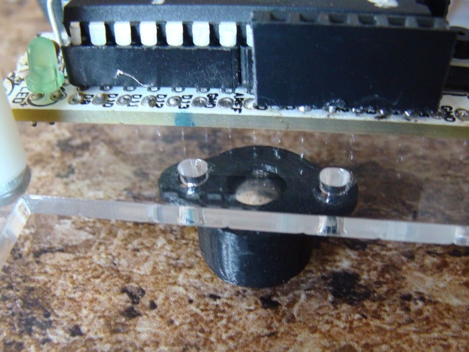
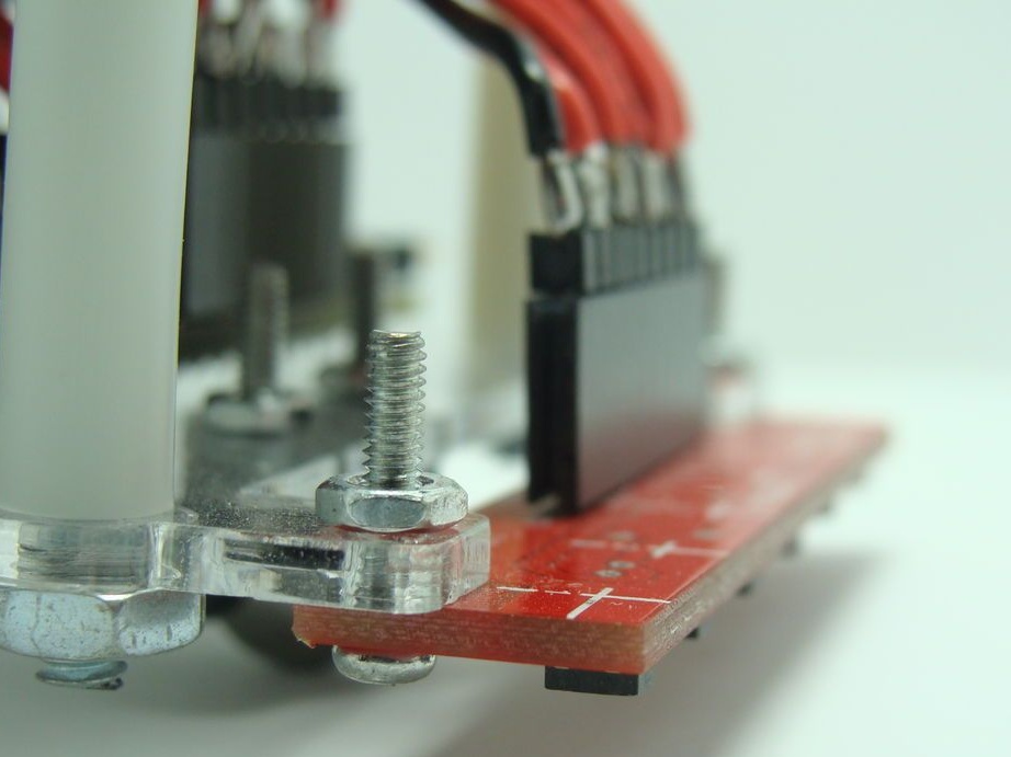
Step Eight. Installation of sensors.
Sensors were bolted to the bottom of the machine. The GND pin is connected to the GND Arduino. Next, the Vcc pin is connected to the 5V Arduino. The Arduino 5-0 ADCs connected the pins of the analog 6-1 sensors.
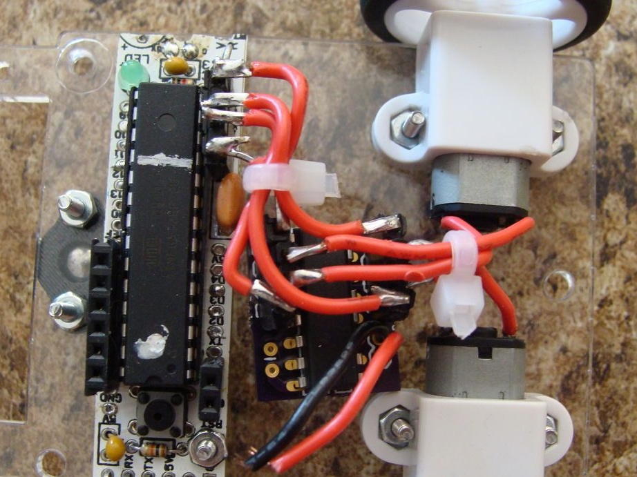
Step Nine. Nutrition.
Arduino just soldered wires from the battery. Turning the robot on and off will be a switch on the battery, so it was decided to use soldering. This completes the assembly of the robot.
Step Ten The software part.
The program has several functions responsible for the operation algorithm. The “left hand” function receives readings from sensors and controls the robot according to these rules. The rotation function is turned on before the robot notices a black line, having noticed that it is traveling straight. A path optimization function is also integrated. The program can be downloaded under the article in the archive.
Robot Video: