

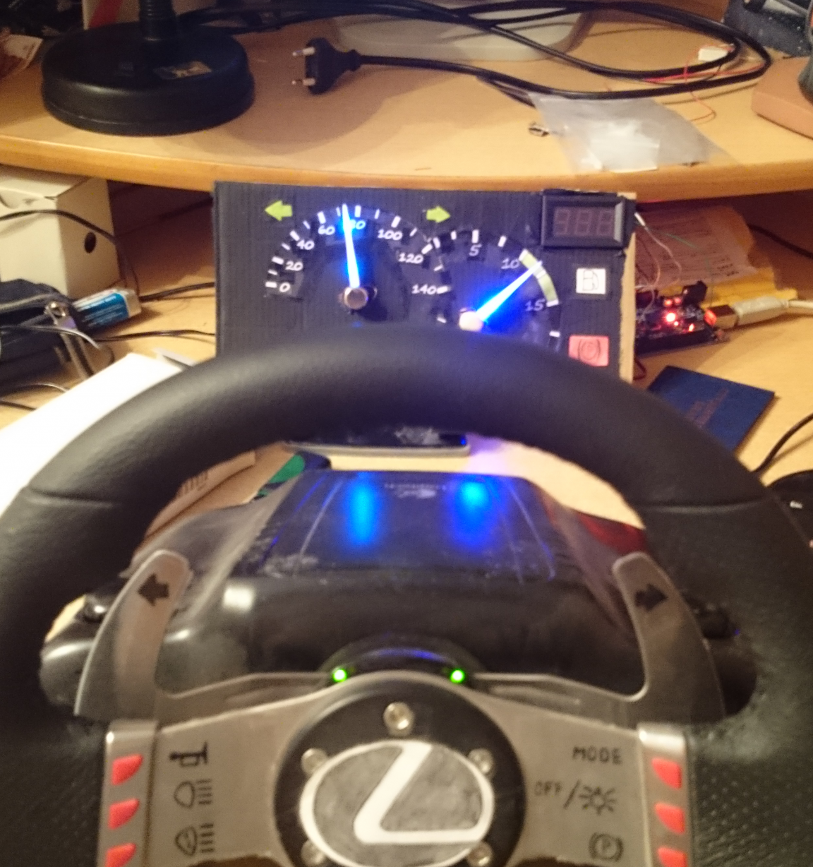
I have long seen how foreigners made car simulators by synchronizing the dashboard from the car with the game. I wanted to make my own design.
So, what I needed for this:
Arduino UNO R3
Wires
Servos (I used SG-90)
Solder
LEDs (2 white, 1 red, 1 orange, 1 blue 3mm; 2 blue smd LEDs)
Resistors (4pcs. Approximately 500 ohms)
Soldering iron
Wire
Cardboard
Glue (super glue)
Stationery.
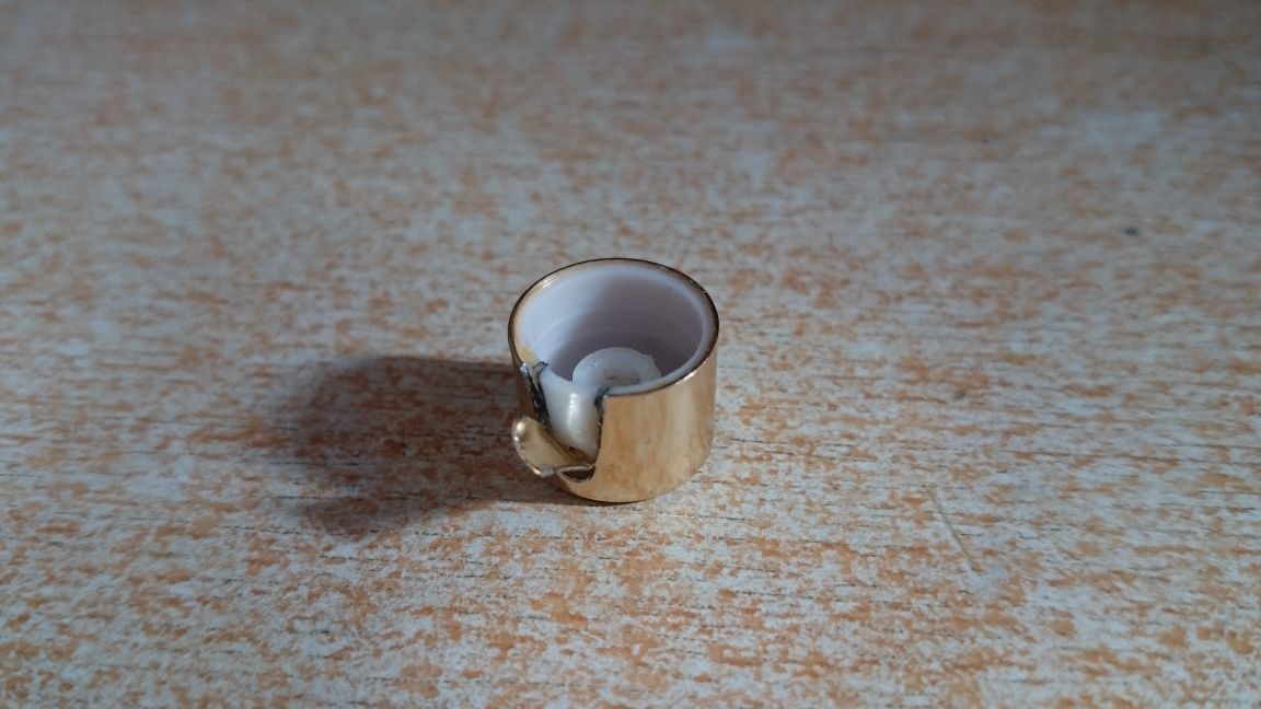
Caps from perfumes (the buttons themselves, where the nozzles are installed)
So let's go:
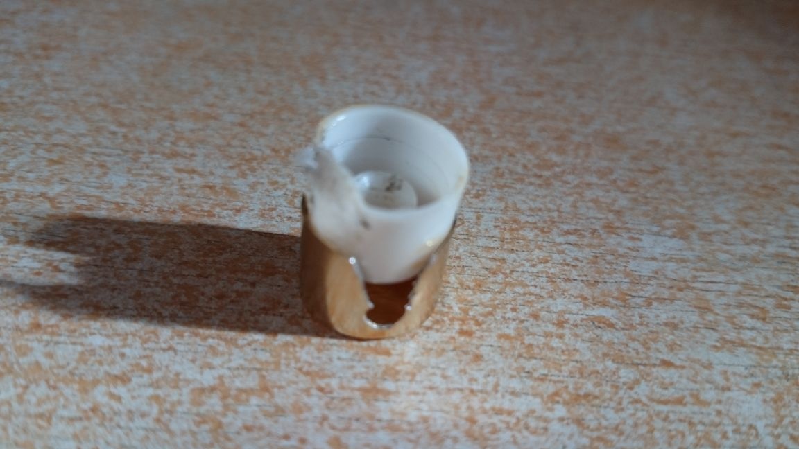
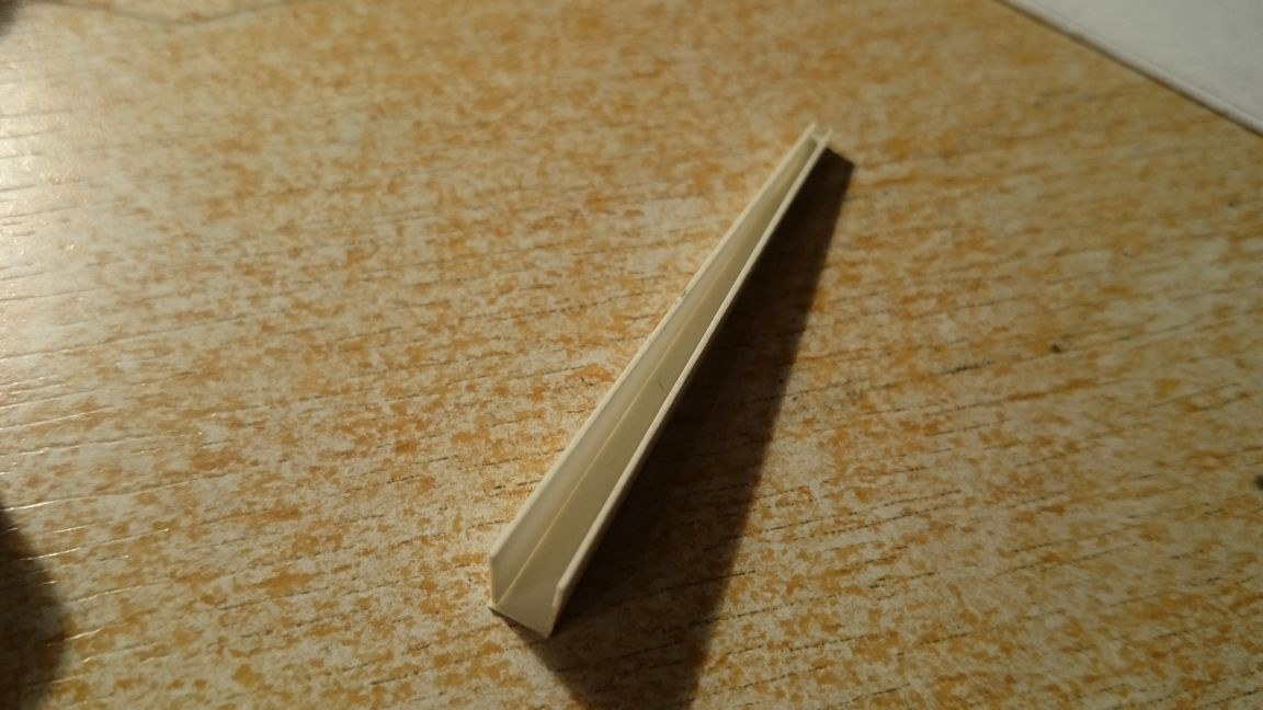
1) We take the caps from the perfume and we need to pull out the insides, for this we make cuts on both sides of the nozzle:
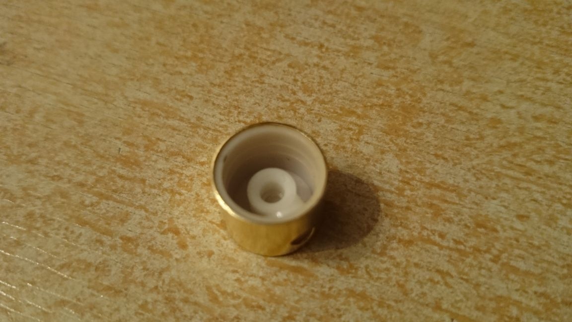
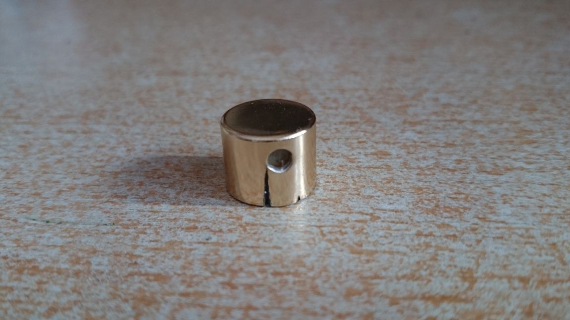
We bend the plate, tear off and pull out the insides, passing the nozzle along the sawn "corridor"
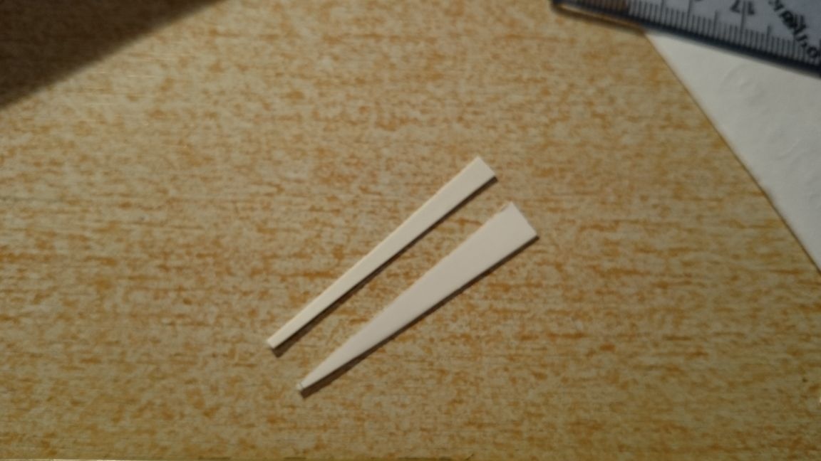
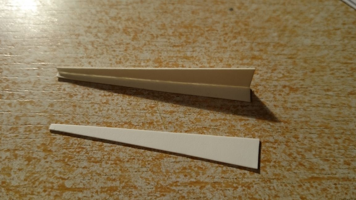
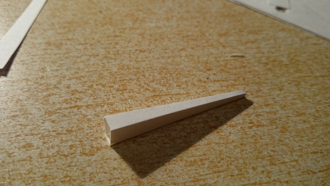
Next, we determine the length and width of the arrow itself, cut out the edges of the arrow and glue it (the upper side is made of plain paper to let light through):
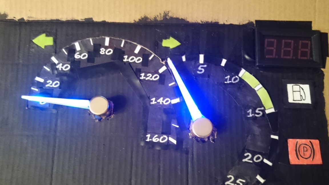
Further, when I was making the first arrow, I used LEDs to highlight smd, connected it in parallel and placed them inside the arrow at the end and at the beginning, thinking that it would distribute the light more evenly, but it turned out that it shines pointwise. The wire was soldered to the conclusions. I did not redo it.
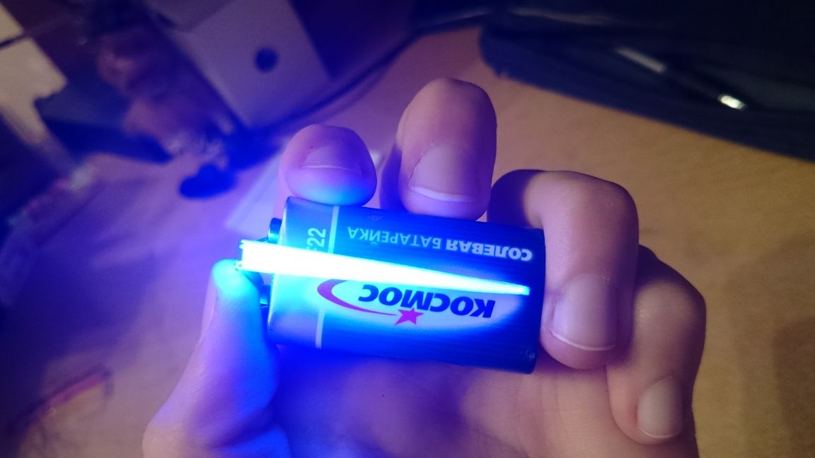
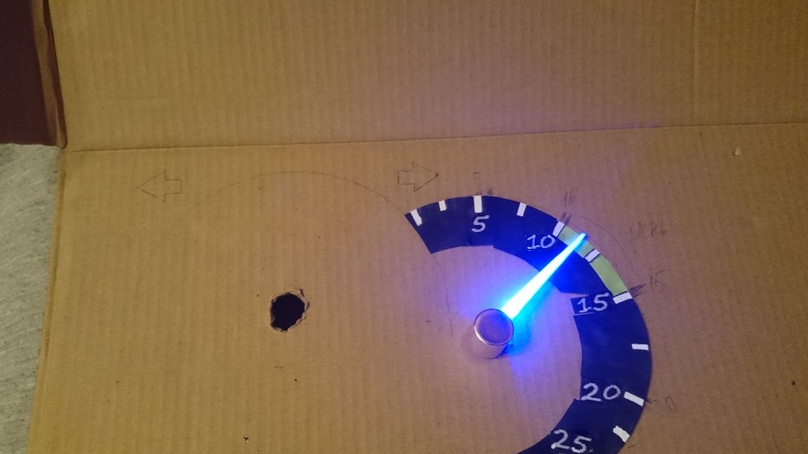
When I did the second arrow, the process is the same, but for illumination I used a 3mm blue LED and just glued it at the base of the arrow, connected it, and ... we got a gorgeous result:
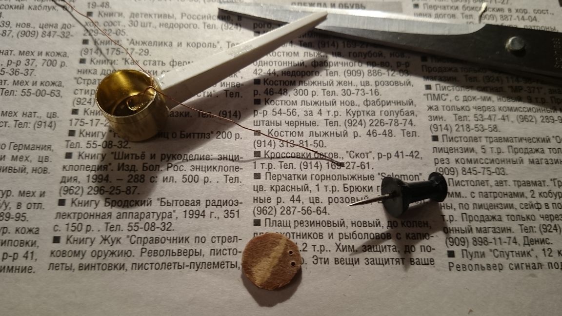
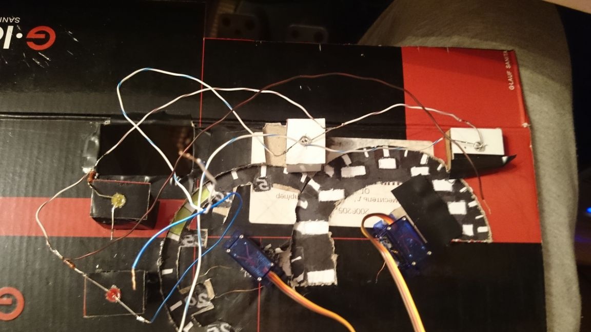
In order to put it on the axis of the servomotor later, I cut a cake out of thick cardboard, made holes in it for wire-leads to highlight the arrows, and in the center there was a hole for mounting on the motor axis:
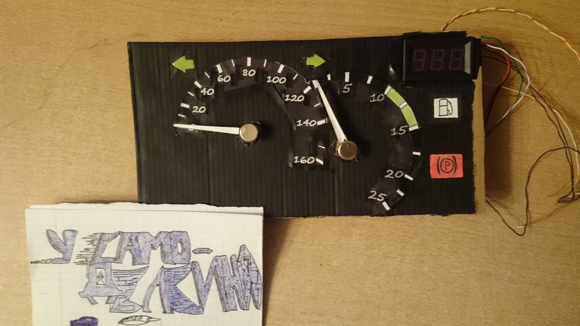
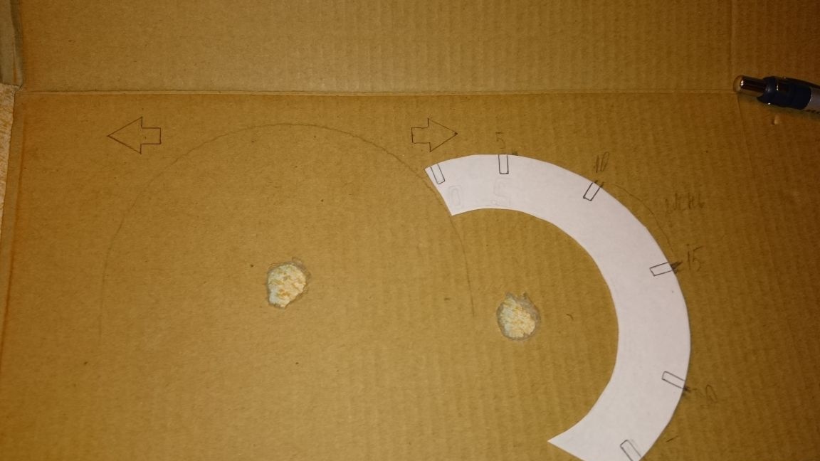
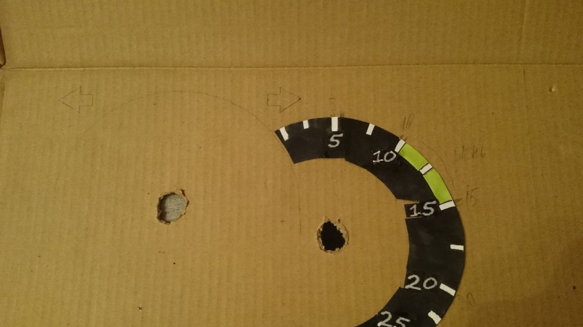
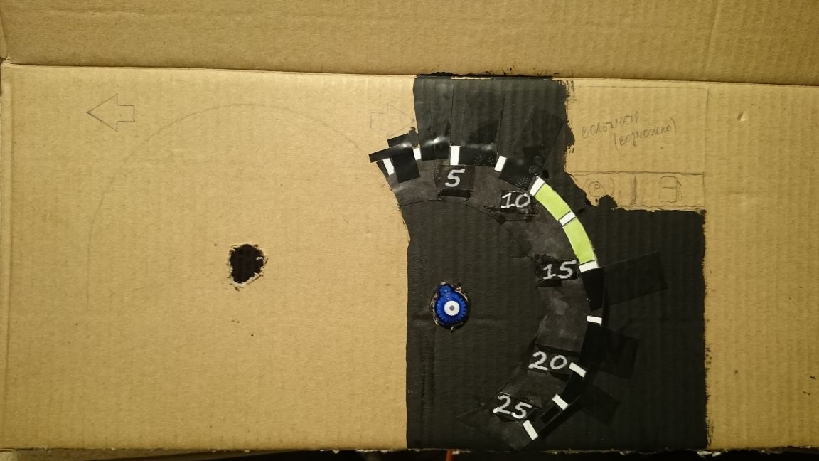
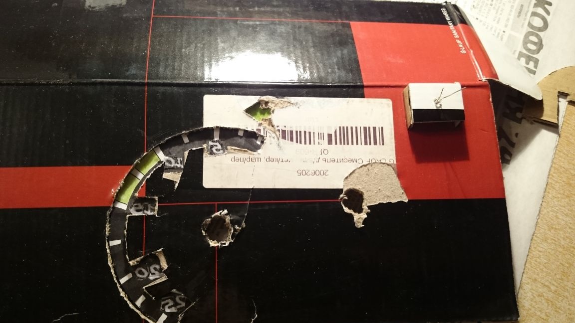
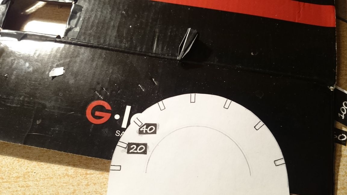
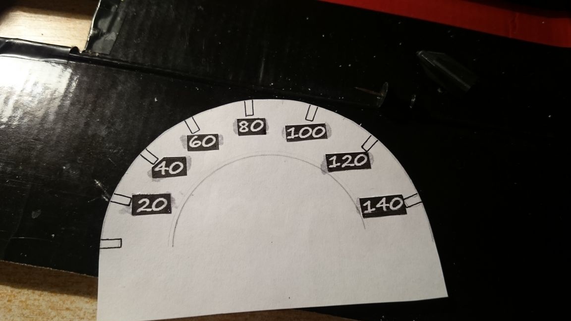
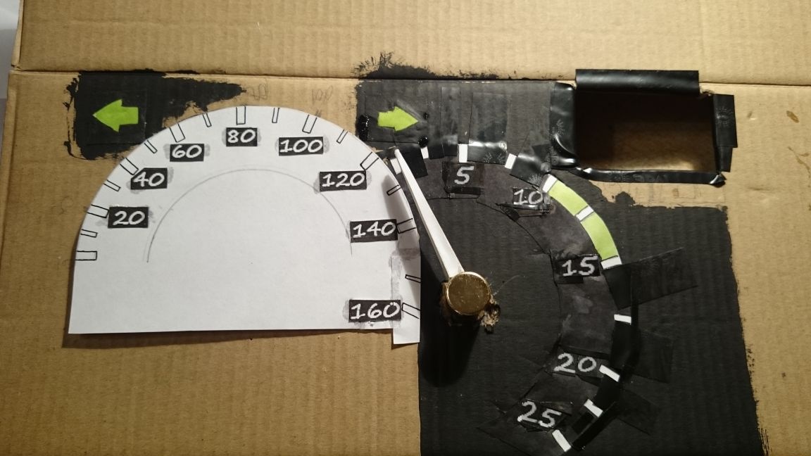
Next we need a bigger cardboard, pretend arrows and draw scales:
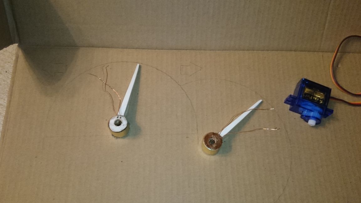
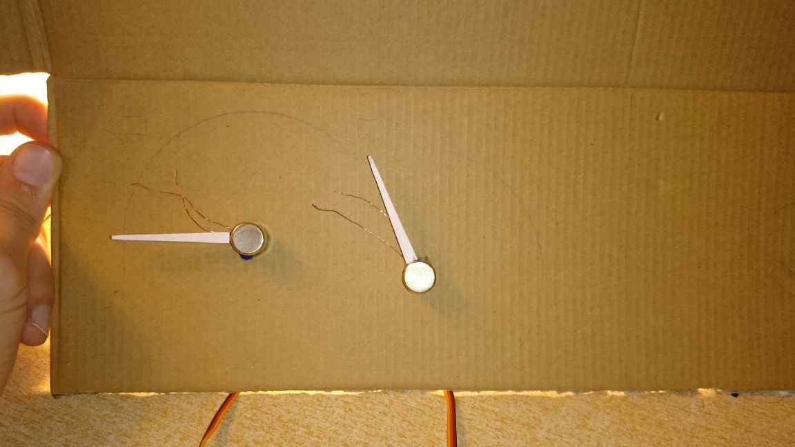
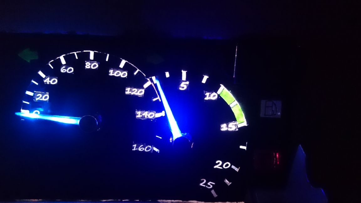
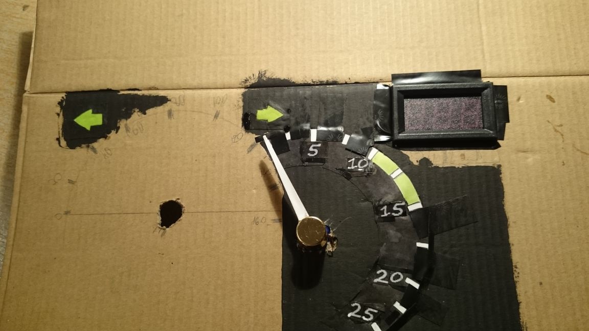
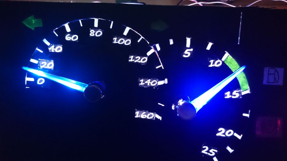
Then I connected the servomotors, put on the arrows, put the “zero” mark on the tachometer and speedometer, started the game, drew points on the tachometer 10, 15, 20, 25. Also with the speedometer. He drowned along the highway, marking points at 20, 40, 60, 80, 100, 120, 140, 160.
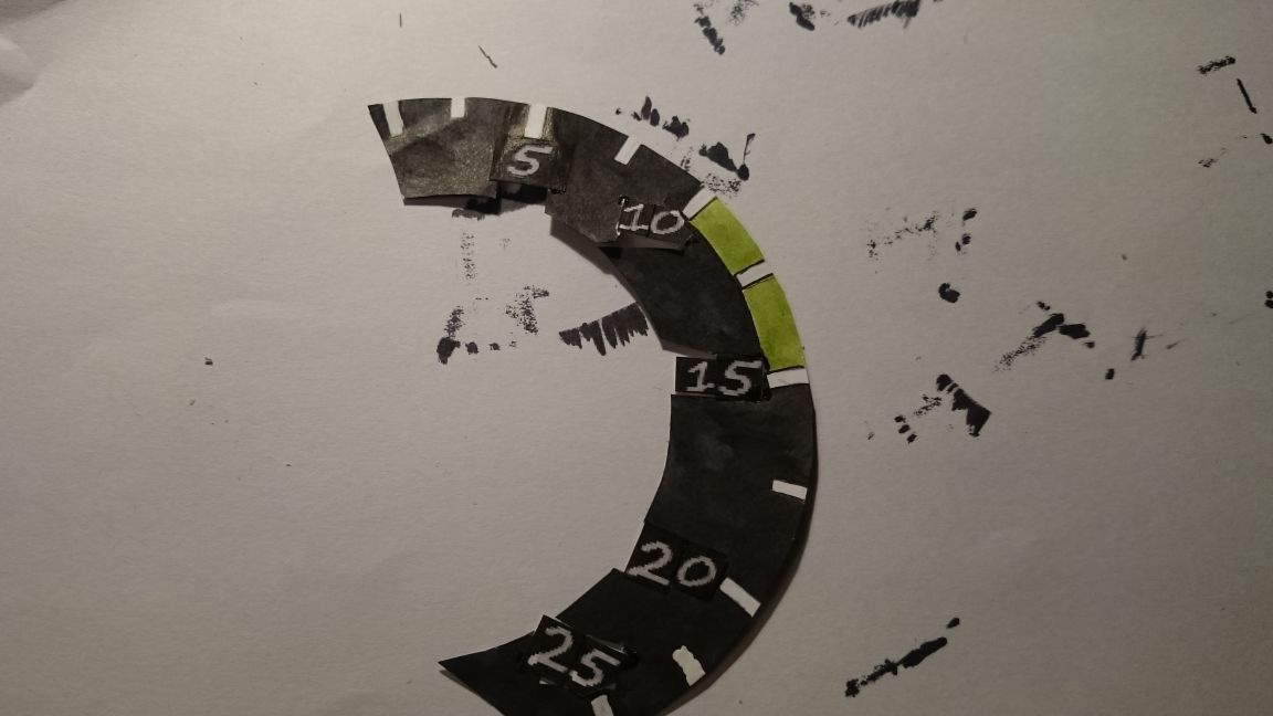
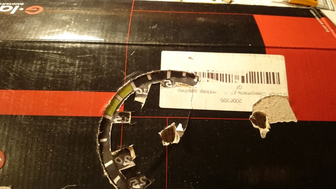
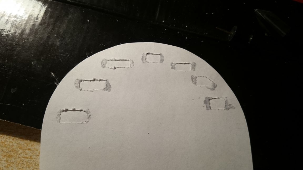
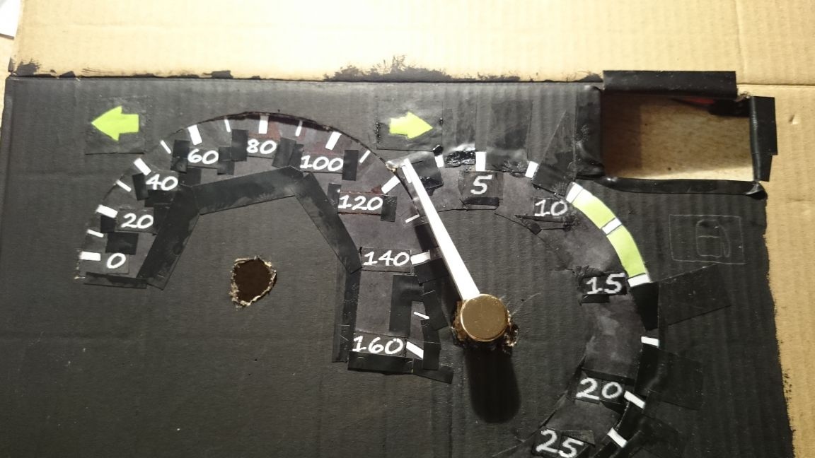
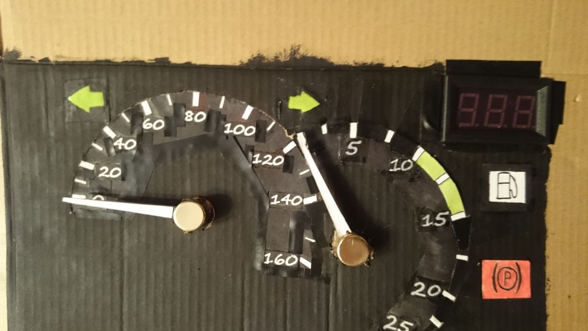
Then I cut out a “rainbow” from paper, transferred all the notes to it and began to cut through the “windows” and stick on the printed numbers, painted everything around with a black marker so that it would not shine through, tried on with an arrow.
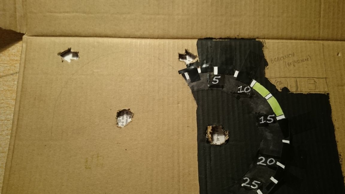
I cut a hole for the scale at the base of the panel to make the scales illuminated, glued painted:
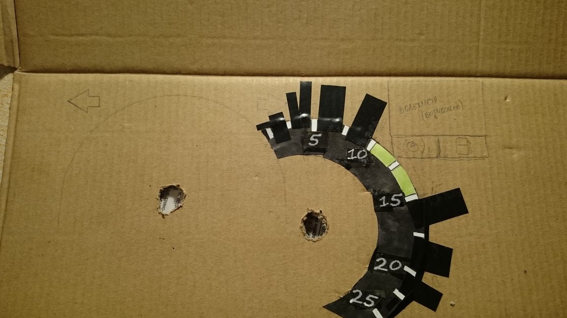
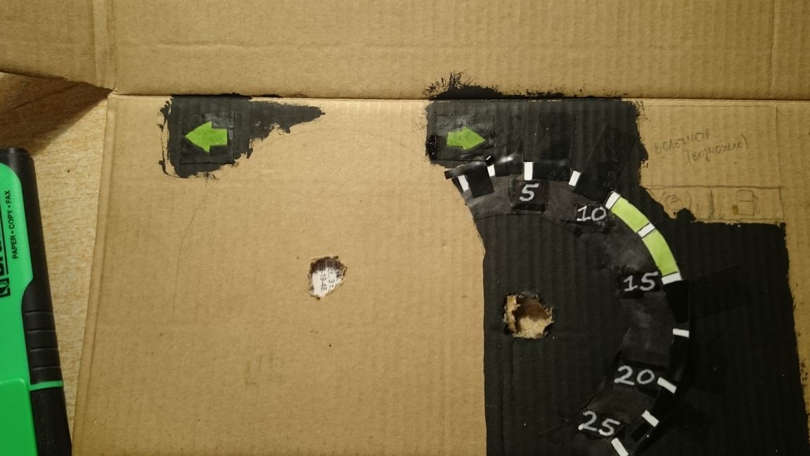
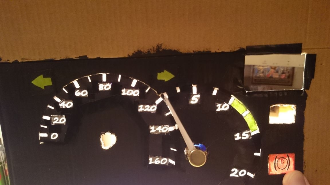
I cut holes for the turn signals, cut out a piece of paper, painted with a green marker, and stuck it:
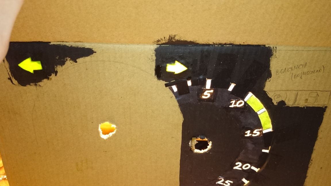
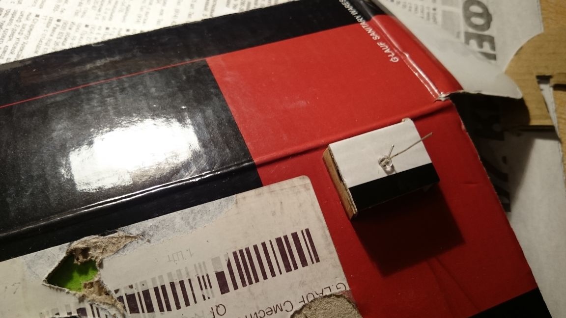
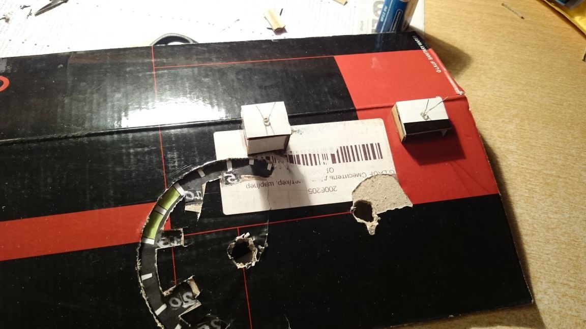
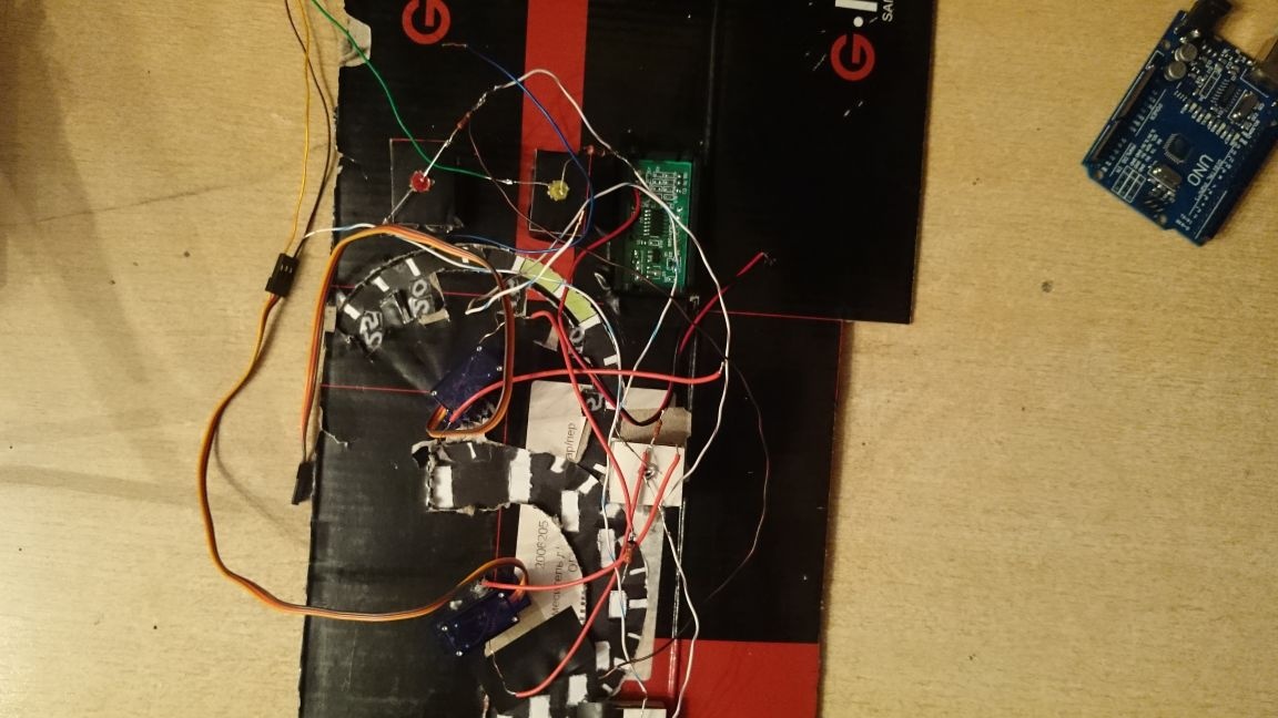
On the reverse side, I made “boxes” for attaching the LED, and so that the light does not scatter and a more uniform illumination is obtained:
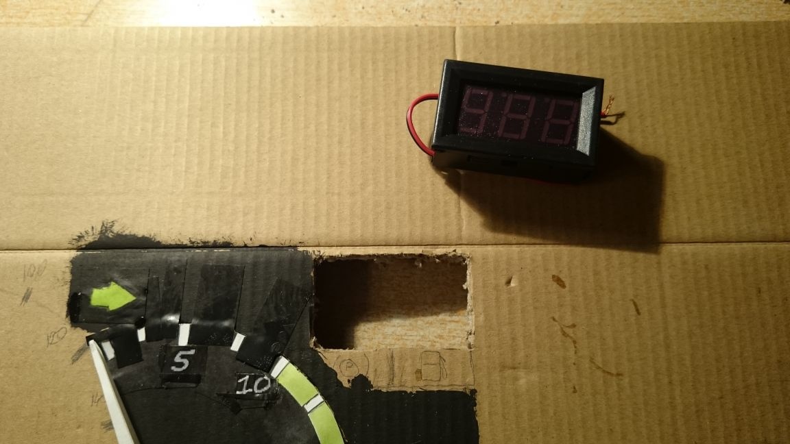
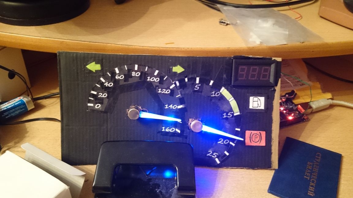
I cut a hole and inserted a voltmeter there.In the future, I plan to make an external power supply for the servo and connect a voltmeter to monitor the voltage that the power supply supplies to the servo:
Then he did the speedometer like a tachometer: windows, glued numbers, then cut out a strip at the base so that the scale appeared, pasted, painted. I glued the servos, let the wire through the backlight arrows into the holes made next to the hole for the servos:
Then I cut out two holes under the voltmeter for indicator lamps, to indicate the activated parking brake and low fuel level. Here, as with the turn signals: I drew an icon, painted the paper, stuck it, the “box” in it had an LED in it, and resistors on the LEDs.
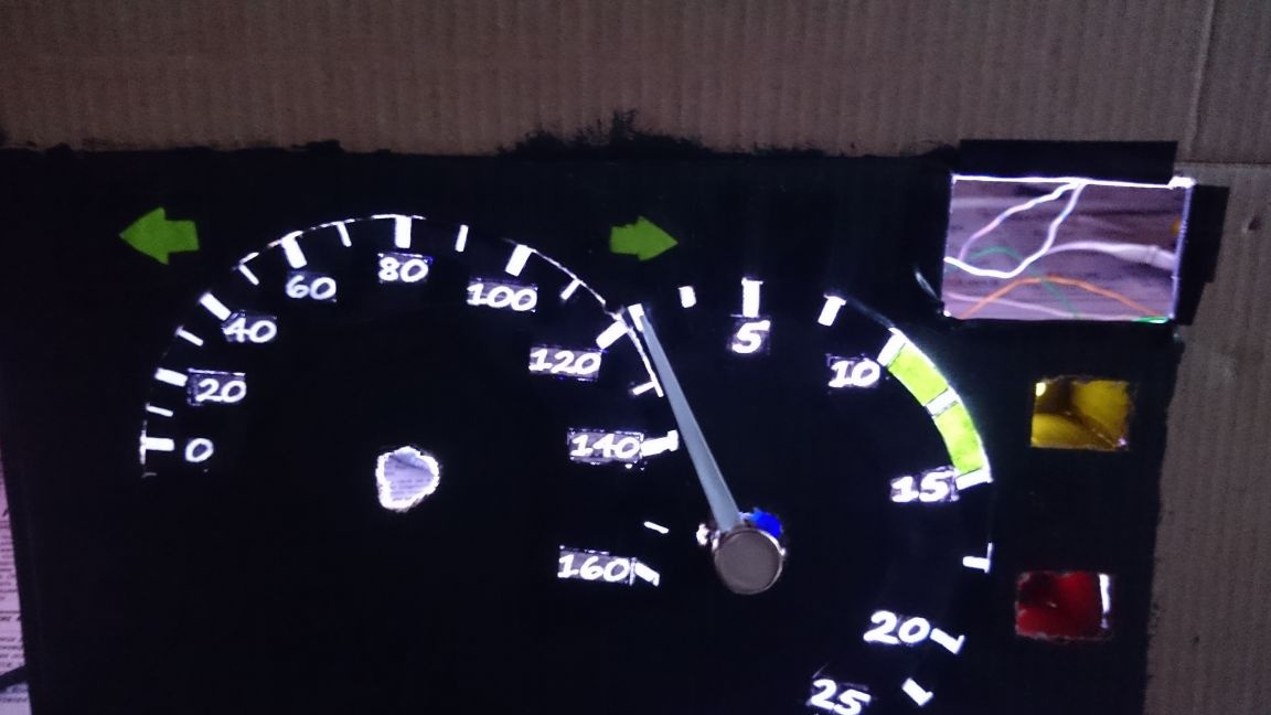
Total:
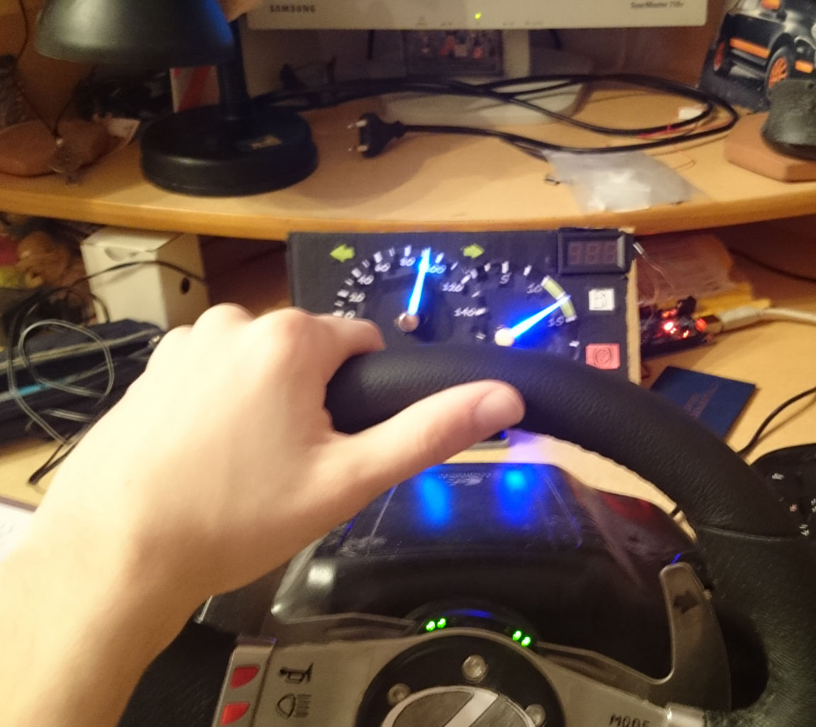
Later I'll upload a video on YouTube. That's all.