
An axial-type wind generator based on a finished hub and a three-phase generator, which contains 15 coils wound with a 0.7 mm wire of 70 turns. The rotor of this generator has 20 pairs of magnets measuring 20 by 5 mm, and the stator thickness is 8 mm. This model uses a two-blade propeller and a system of protection from strong winds.
Materials and assemblies used to build this wind generator:
1) car hub
2) epoxy resin
3) metal corners
4) magnets of size 20 by 5 mm in an amount of 40 pieces
5) pipe 20
6) superglue
7) petroleum jelly
8) a nave from the "cramming" trailer
9) plywood
10) laminate 8 mm
11) wire 0.7 mm thick
Let us consider in more detail the main stages of construction and design features of this model of a wind generator.
To begin with, the author took up winding coils for the stator. To facilitate this process, the author made a special device:
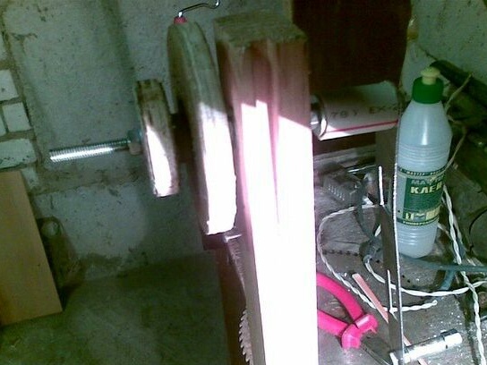
For its manufacture, the author used a pipe with a diameter of 20 mm, so it just fits the size of the magnets. The author decided to make coils 7 mm thick.
Another image of a homemade coil winder:
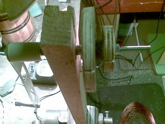
The author notes that thanks to this machine, assembled from improvised materials, the winding of the coils passed without any special difficulties. The main thing is to wind coils round to round giving a slight stretch so that the coils are pressed more tightly against each other.
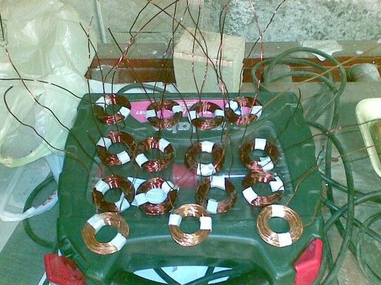
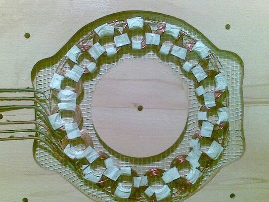
So the author began to manufacture coils for the generator. In order to prevent the coils from falling apart after winding, the author smeared them with glue for plastic, and also wrapped them with window tape. For winding coils, the author used a wire 0.7 mm thick with 70 turns per coil. Although after the final assembly, the author decided that it was necessary to do 90 turns each, this would allow to win by voltage.
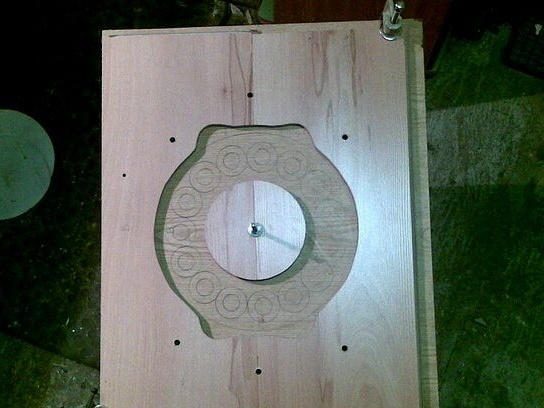
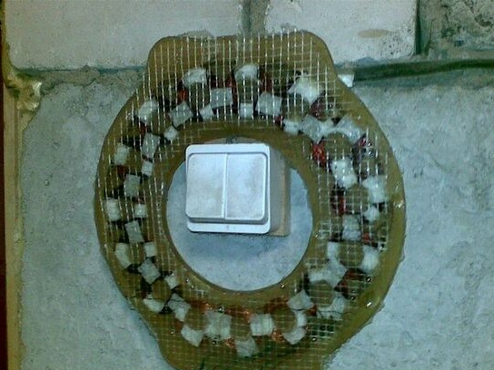
Next, a mold for filling the stator was made. The author decided to make a form on a plywood substrate. To do this, plywood was marked on the plywood, which will more accurately place the coils. The middle part of the mold is made of 8 mm thick laminate. In order to prevent the epoxy from sticking to the mold, the author lubricated it with petroleum jelly, this will then make it easy to remove the stator from the workpiece after the epoxy hardens.
For wires, special grooves were made using a grinder.
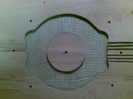
When pouring the stator, the author used fiberglass to increase the stator strength. Having laid the fiberglass mesh on each side of the stator, the author pulled the lid through pre-drilled holes and left the stator to cool.
The stator coils were connected in phase, all six wires from the phases were brought out through the grooves, after which the wires were smeared with plasticine so that the resin did not leak. Subsequently, the author connected the phases by a star.
The next day, the stator was removed from the mold, and the author slightly worked the edges for evenness. The author also decided to fill the magnets on the disks with epoxy resin for greater reliability.
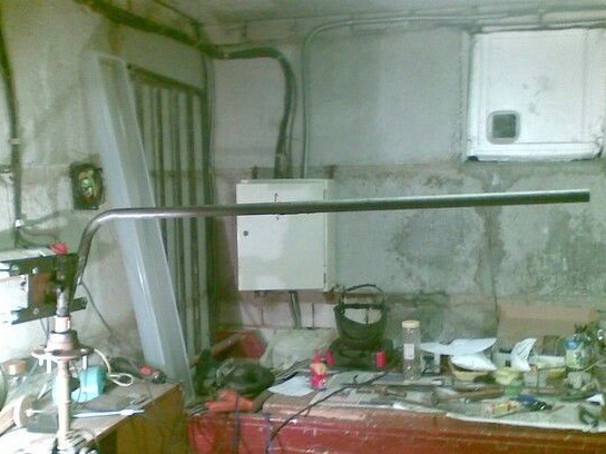
In the photos below you can see how the rotary axis of the wind generator was made:
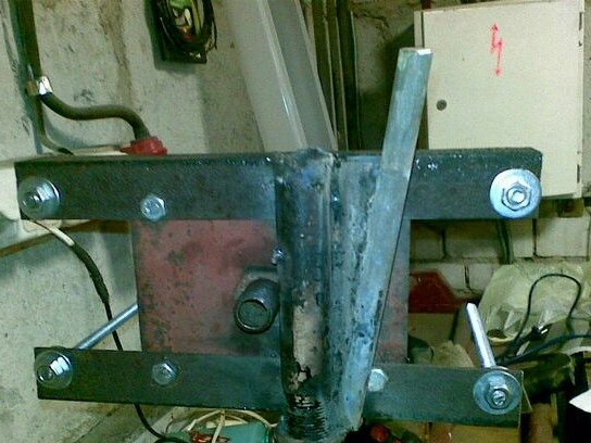
The basis for the manufacture of the rotary axis was the automotive hub. In order to protect the future wind generator from too strong winds, the author used the standard design of wind removal by folding the tail. It is important to note that the wind head must be removed at least 100 mm, otherwise the wind protection will not work as the generator axis will be too close to the rotary axis.
Also, a pin was welded to the structure at an angle of 20 degrees and 45 degrees relative to the screw, the tail of the wind generator is put on this pin.
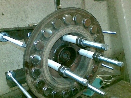
Consider the design of the hub of the generator.
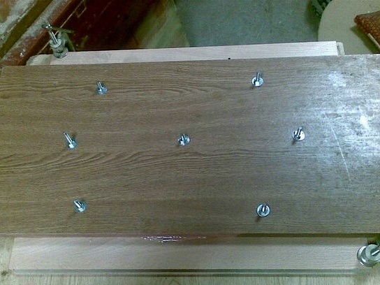
The hub from the Zubren trailer was taken as the basis of the generator itself. The author used magnets measuring 20 by 5 mm. Each disk took 20 of these magnets. The hub was twisted through a plate on which the corners were attached. The stator of the generator will be held on studs.
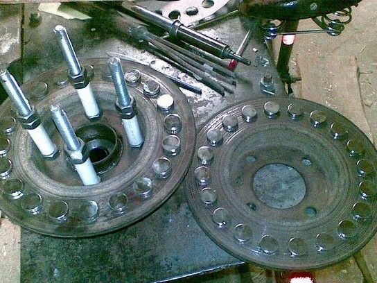
Further, the author began to manufacture disks with magnets.
The magnets were attached to the discs using superglue. In order to do everything as accurately as possible, the author made a template from cardboard. It is also important to note that the magnets must be glued with alternating poles, so that the discs with magnets are attracted to the generator.
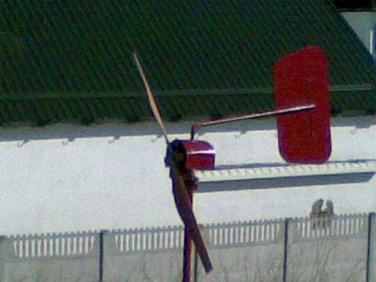
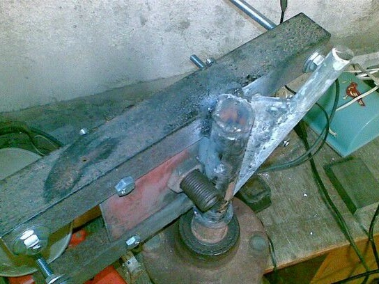
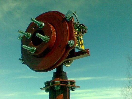
Below you can see how the tail of the wind generator was fixed, which will protect it from strong winds:
In the photograph, the wind head was placed too close to the rotary axis of the wind generator, which was subsequently identified during testing and eliminated. However, the tail mount and tilt angles are correct. After bringing the design to mind, she showed herself perfectly: when the wind intensifies, the screw turns away, and the tail folds and rises.
The author decided to start with a two-blade version of the screw for his generator. The blades were made of PVC pipe. A casing was also built that would cover the generator from rain.
Then the generator was assembled and painted. After painting, the author decided to test the operation of the generator. By hand, it was possible to spin the generator up to 30 volts with a short-circuit current of 4.5 A.
This generator works on 3 LED strips of 25 watts each, but in the future the author plans to take a more serious approach to calculating the screw for the generator and connect the battery.