» Electronics » LEDs »How to light two 3-watt LEDs from one battery

How to light two 3-watt LEDs from one battery


If you ever want to power the LED from a single battery, then sooner or later you will come across a circuit called Joule Thief is a thief of joules. This circuit is good for many: with a small number of parts, you can use a dead battery, the assembled design is compact and will work on a battery with a voltage of only 0.6V. The classic circuit of this device can be viewed on Wikipedia. There are many options for this scheme, attempts to optimize it. I will show you with one of the options for this design, which will light up two 3-watt LEDs connected in series. Everything was assembled quickly. Given the rewind of the throttle, it took 20 minutes.


What is needed for assembly:

Soldering iron, not a lot of solder and wires. Battery 1.5V or less, firm hands.
Transistor. I used the CT630,

How to light two 3-watt LEDs from one battery


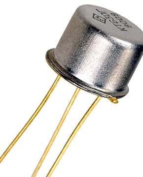
its maximum operating frequency is large, the collector current is higher than that recommended in standard schemes. In principle, any NPN transistor with a gain of at least 150, for example, 2SC1815, can be used. One 10 kΩ variable resistor.


One electrolytic capacitor 47 uF at 25V. A larger capacitor charges longer and reduces the brightness of the glow. Any one diode with a reverse voltage of at least 100 V, because without load, the capacitor charges up to 30-45V.


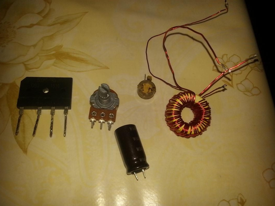
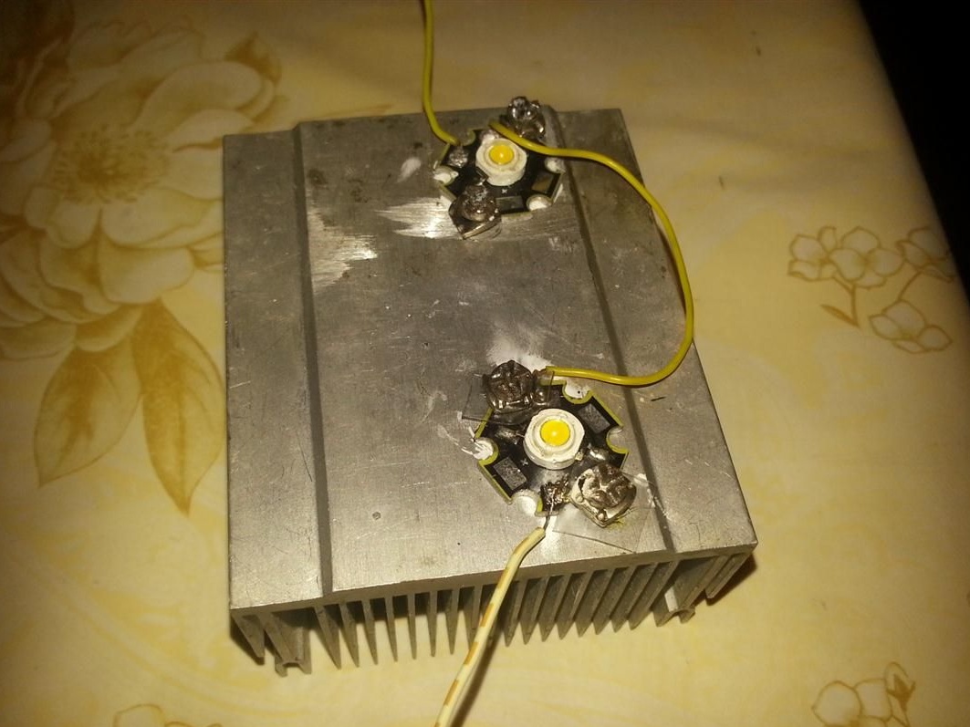
One capacitor 0.01 uF. Two 3-watt LEDs connected in series. Mounted on a heat sink from a computer processor.


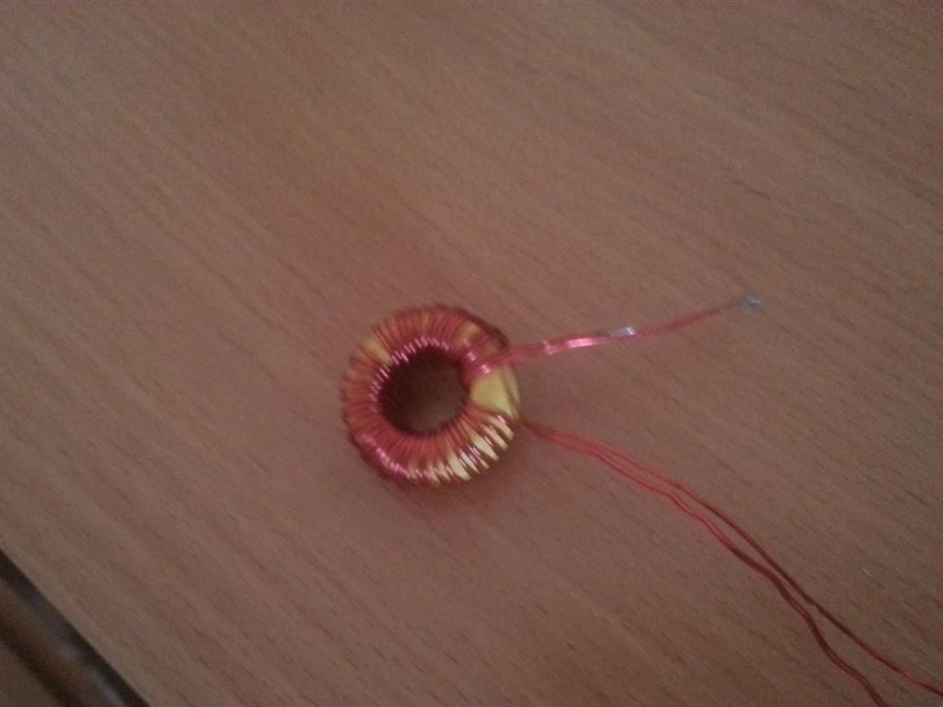
One group stabilization choke from a computer PSU.


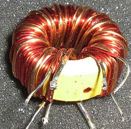
You can use any ferrite ring that is at hand. I used the choke from the PSU, simply because it was. I did not count the number of turns, I just wound the entire wire from the ring (there are two wires of different cross-sections) and wound it again, bifilar.


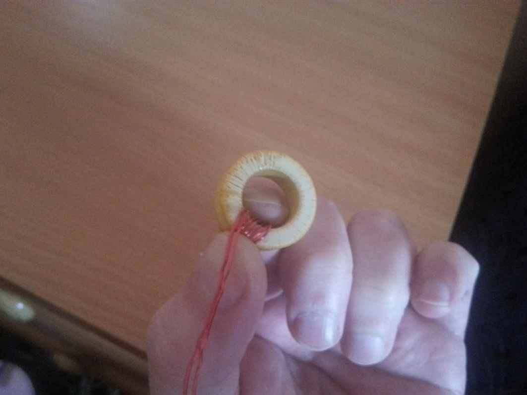
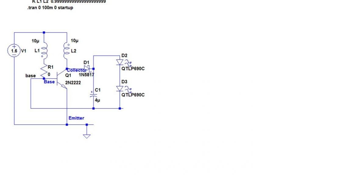
A winding wound with a wire of a smaller cross section was included in the base circuit of the transistor. Accordingly, the second winding is included in the collector circuit. It is important that the beginning of one winding is connected to the end of the other, as shown in the diagram.you can wind a winding on a ferrite core with a tap from the desired number of turns, or in general, make a coil without a core.

Unlike the standard circuit, here, the load is connected between the base and the collector. The efficiency of the circuit depends on the capacitor, which is connected in parallel with the load. Such a load switching circuit was made in an attempt to use the OEDS arising in the L2 coil.

The video shows that when the resistor R1 is closed, the brightness increases.

In principle, it is not needed at all, because In the diagram, it limits the current through the base. The KT 630 transistor feels great even without this resistor.

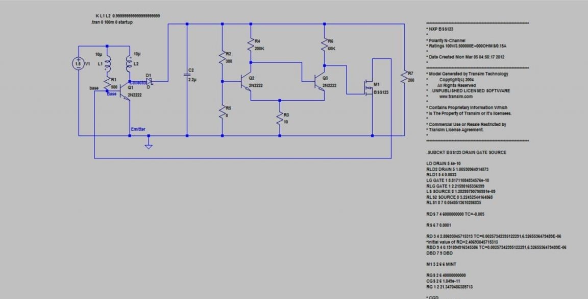
And in conclusion, another circuit with adjustable output voltage
3.5
2
3

Add a comment

    • smilesmilesxaxaokdontknowyahoonea
      bossscratchfoolyesyes-yesaggressivesecret
      sorrydancedance2dance3pardonhelpdrinks
      stopfriendsgoodgoodgoodwhistleswoontongue
      smokeclappingcraydeclarederisivedon-t_mentiondownload
      heatirefullaugh1mdameetingmoskingnegative
      not_ipopcornpunishreadscarescaressearch
      tauntthank_youthisto_clueumnikacuteagree
      badbeeeblack_eyeblum3blushboastboredom
      censoredpleasantrysecret2threatenvictoryyusun_bespectacled
      shokrespektlolprevedwelcomekrutoyya_za
      ya_dobryihelperne_huliganne_othodifludbanclose
25 comments
Skybark
No, no, shy ...))))
Or do I not understand something? a?
A bright thought flashed here - 6 W = 1.5 V x at a speed of amperes ?? = right! 4! And where to put efficiency?
Or is the law of conservation of energy not fulfilled in the world ??
So Ivan’s remark
But the transistor and LEDs do not fade, including due to the fact that the battery is half-dead with a large internal resistance.
It would be interesting to know what current actually flows in different modes of this device.
quite appropriate.

The public needs an explanation! (from)
qwenter
The author, do I understand correctly? According to the first scheme, the current from the LEDs flows to the connection point of the base of the transistor and the base winding of the transformer. Shouldn't it drain onto a common wire (ground)?
Given the resistance of resistor R1 at 0 ohms, current continues to flow along the path of least resistance. Through the base winding back to the collector winding?
Quote: "or even, make a coreless coil."
Quote: “In principle, it is not needed at all” (R1)
Quote: "will run on a battery with a voltage of only 0.6V"
And without what else will it work? Will there be no battery?
Qitaa: "will operate on a battery with a voltage of only 0.6V"
It would also be interesting for me to find out the operating time (6W = 1.5V X 4A), or am I not catching up with something?
Regarding unconnected coils without cores .... This will also work, only the number of turns will be two times more.

Please joke?
MAN !!!
Pronin - the number of homemade products 1. (causes doubt in its relevance).
Ivan_Pokhmelev - the number of homemade products 0.

Well, you really are "music critics." As people say: - Well, who would mumble ...
I want to answer in your words: - "
You can continue to remain in your delusions. ((
Success to you1
Author
Mr. Pronin, pearls in a type article
separate source
?? Does this need to push young people?
Author
the photo shows the details (diode bridge, Rvar (10Kom) !!) 2sc1815.
. Well, read carefully. It is possible without it.
Author
Wow What a debate. Why sophistry? I suggest to collect. Make sure everything works. Get into Wikipedia, read what and how. For Ivan, you can write a master class, for example, by Siemens Logo. Your profile. People would come in handy. Smart home to assemble there. Regarding the scheme. Everything works. My hands are on the video. 1.5 volt battery It still works. Use when there is no light. There are no necessary tools, so I did not measure currents. And there is no time with work. The new workshop, you know, butter. Automate a little. Regarding unconnected coils without cores .... This will also work, only the number of turns will be two times more. No time for small projects? Have fun big ...
What is "not entirely competent" in my reasoning?
The diagram at the end is, apparently, the source by which this homemade product was made. Only there is an input OS.
The author of the homemade product has a simplified blocking generator drawn, which, if successful, can even possibly work for some time. Although, the circuit of the classic blocking generator is already so simple to disgrace, but there every element is in place. And here....
In addition, as you rightly noted, the bloopers are the sea. I add that in the source there is a Schottky diode, and the author offers "any diode with a reverse voltage of at least 100 V", without saying anything even about the current. And about the winding of the transformer at random, I generally keep quiet. And the diagram does not depict trance, but two separate coils without cores.
But the transistor and LEDs do not fade, including due to the fact that the battery is half-dead with a large internal resistance.
It would be interesting to know what current actually flows in different modes of this device.
The article, so to speak, is crude. Even decoration - the photo shows the details (diode bridge, Rvar (10Kom) !!) 2sc1815 ..., which are not needed. And why then are they ?? And the diagram at the end, for which ??
I modeled this “circuit” in Multisim 12 ... This is inclusion through the base ... Nothing good.
: winked:

Pronin! Explain your position, but somehow Kuce, you expressed your thought. Only briefly, if possible. Is this circuit operational or not? We will not go into details.
I think the critic Pohmelev is absolutely right. Although the admin says that "delusional" notes do not pass ... Alas, there are such pearls and errors.
: winked: Ivan! Come on? So "plow" 20 years, that you don’t take your head off, that you have no time to tear off (as you put it). Or maybe you're just in this department () work?
You, after all (as a cool special), also do not quite competently argue. Yes, and the discord began not with that. It seems to me that you are not involved in such small things, because of the inability to collect even them. Sorry if WHAT ?!
I have been developing automation and measurement systems for over 20 years. And I don’t have time to practice small crafts and their descriptions. And young people who are interested in electronics should be sent in the right direction.
I do not troll, but criticize in terms of competent product design.
You yourself say that the maximum current is 0.3 A, and it all passes through the transistor BE transistor, which works exclusively due to the technological reserve with respect to the guaranteed parameters.
smile Musical critics, as a rule, “didn’t give birth to anything themselves. They only criticize (they studied for this). I’m why (I don’t want to offend anyone), I also often want to look at“ THEIR NEEDLEWORK. ”But you need to criticize (discuss) , while it is advisable to understand
in this or repeat what was suggested by the author.
Author
For starters, you would try to lay out something of your own. Just troll)))
Author
Even so. Well, there is a resistor in the base circuit there. Have you seen? Here they can set the base current. What is in the way? I am happy with such a job. Nothing burns out.
The maximum current of the KT630 ​​base is 0.2 A. You have the entire current of the LEDs being closed to minus the source through the transition of the BE transistor.
Author
what currents? There is a maximum of 300 mA. I still have not faded. Doesn't even get too hot.
The circuit does not match the description. KT630 ​​will burn out on the base, because it is not designed for such currents.

We advise you to read:

Hand it for the smartphone ...