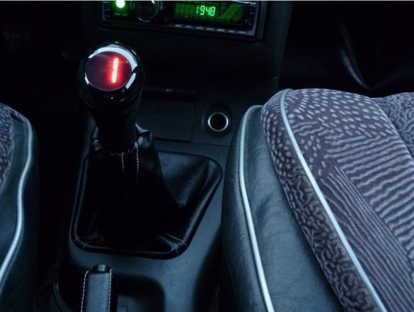
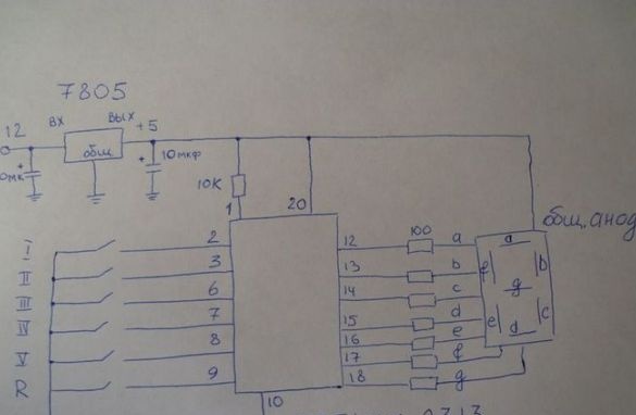
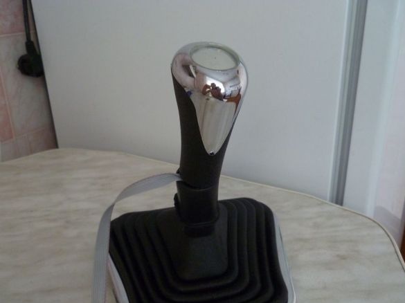
In order to make such a homemade product, you will need some skills in working with the microcontroller, specifically here the AVR microcontroller is used. The system turns on when the ignition is turned on, while power is supplied from the lock to the controller. Data from the shift knob is read through the reed switches. There is a magnet in the sandpiper and when it approaches one of the reed switches, it activates it (closes) and then the system determines based on these data which transmission is engaged. If not one of the reed switches is closed, then the handle is in the neutral position, while a snake runs on the indicator screen. Consider in more detail the process of creating a homemade product.
Materials and tools for assembly:
- LED indicator with a common anode;
- microcontroller ATtiny2313;
- reed switches working on circuit (6 pieces);
- voltage stabilizer type 7805;
- capacitors at 100 and 10 microfarads;
- current limiting resistors of 10 kOhm (1 pc.) and 100 Ohm (7 pc.);
- two magnets;
- A set for the gear lever Turkish production SAHLER (costs about 300 p.).
Homemade manufacturing process:
Step one. Create a board
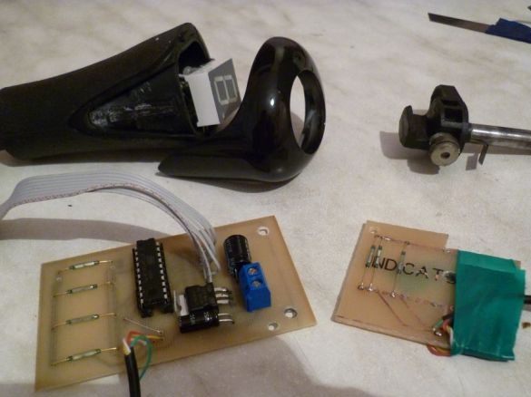
The author made the board out of foil textolite, and on it are reed switches. As for the magnets, they are mounted on the wings.
Step Two Set the indicator in the pen and assemble electronic part of the system
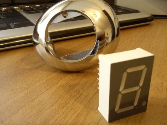
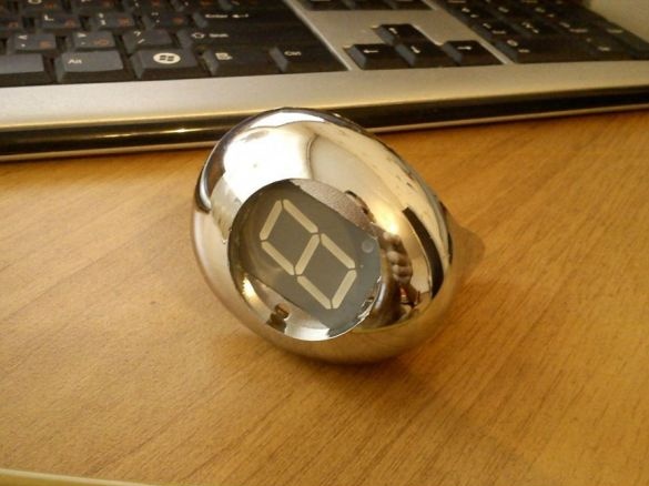
The purchased set for the gear knob, which is recommended to be used by the author, is completely collapsible and very promising for various home-made products. The digital indicator needs to be placed in the handles, it fits perfectly with it. To install the indicator, you need to remove the round plastic cover from the handle, put in its place a glass from plexiglass, which can be cut do it yourself. A film is used to tint glass, it is glued from the inside.
In order for the indicator to sit as it should, in the handle with a file you need to make a seat for it. Next, eight wires are laid in the handle, which are then connected to the controller.
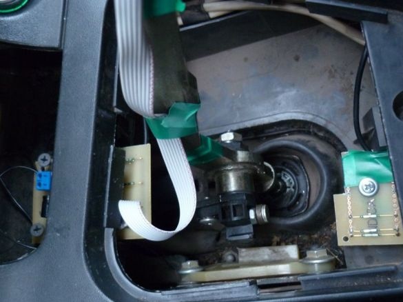
Now you can begin to mount the board with four reed switches.One board is attached to the plastic tunnel under the ashtray using self-tapping screws. From the end you need to make a hole so that the board crawls through. The second board is also attached to the plastic with screws, together they are connected using a black wire. Reed switches can be arranged in another way, for example, put on glue. The most important thing is that the reed switches clearly respond to the magnet.
Step Three Getting started programming the controller
When you turn on the system without programming, it will not work, but this process is not so complicated, for these purposes you will need:
1. A programmer is a device that connects a microcontroller to a computer. Using the programmer, firmware is downloaded to the controller. Programmers are diverse, simple, you can even do it yourself. The author uses the USB AVR910 programmer, you can buy or assemble it yourself, there are schemes and firmware on the Internet.
2. The software with which the programming process will take place. The author uses the CodeVision AVR software.
3. Well, you also need firmware, it is attached.
To connect the controller to the programmer, an SPI interface is used. In the photo on the left you can see the debug board, on the right is the programmer.
The debug board for ATtiny2313 is very simple, here is its diagram.
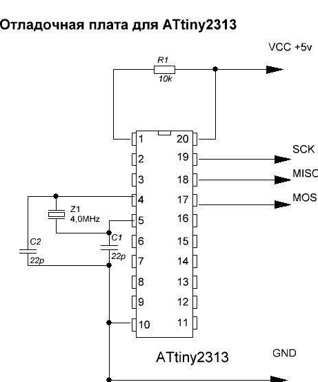
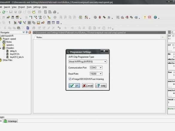
After the programmer is connected to the computer via the USB port, and the microcontroller is connected to the programmer through the debug board, you can start the CodeVision AVR software. In it, go to the Settings section and select Programmer. What settings to enter can be seen in the photo.
Next, open the Tools tab and select the Chip Programmer in it.
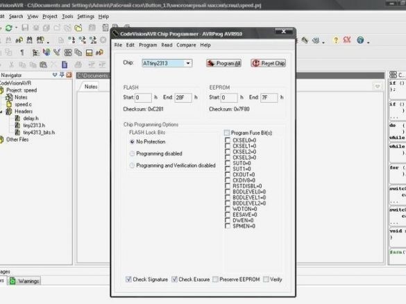
In the Chip window, you need to select the desired controller, in our case it is ATtiny 2313. To check whether everything is connected correctly, you need to click Reset Chip. There should not be a single error. After that you can program.
If the chip needs to be cleaned, in the Program tab there is an Erase Chip function.
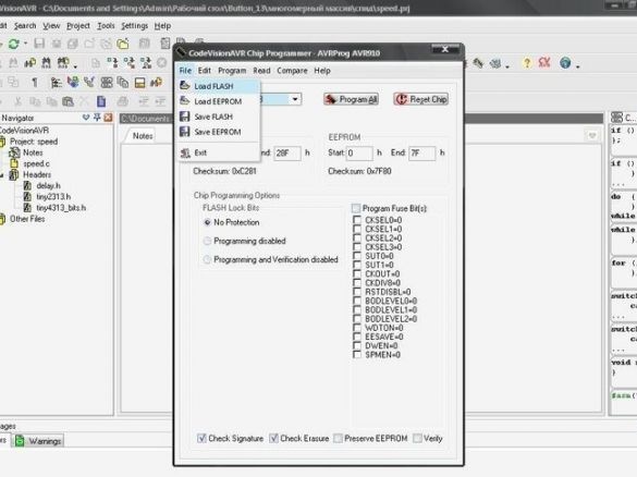
For firmware, open the File tab, then select Load FLASH and select the desired firmware file. To start recording, in the Program tab there is a FLASH button, the process will be displayed on the screen. After that, the controller will be programmed and now it only remains to install it in its place.
This is how you can tune the handle of your car. By the way, in the same way, you can install the indicator in almost any car.

