
In the video you can see how the robot works. It gradually changes color during operation.
Materials and tools for assembling the robot:
- U-shaped mounting brackets;
- four 1.5V LR44 batteries each;
- multi-color RGB-LED with switching function;
- insulating tubes;
- steel pushpin;
- low-voltage motor type RF-300CA;
- button to turn on the robot (with two leads);
- wires for connecting the engine;
- flashing alarm LED.
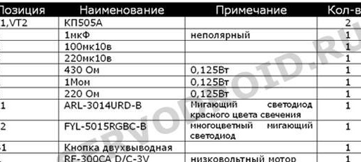
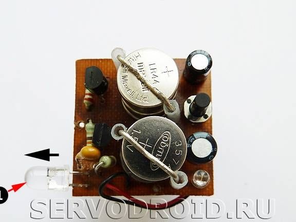
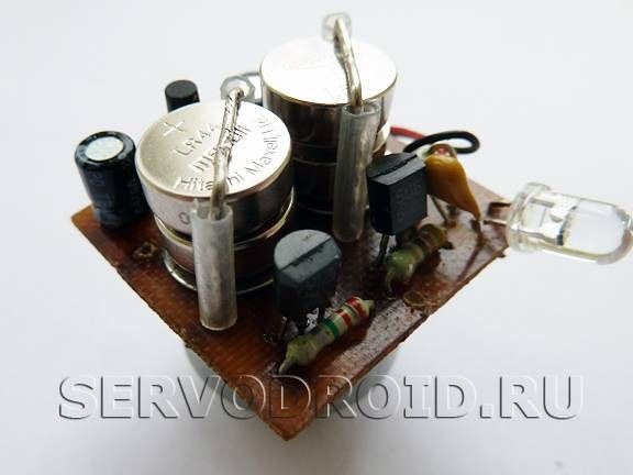
Regarding the necessary electronic elements, they are shown in the figure. The printed circuit board is made of a foil sheet of PCB, its dimensions are only 30X30 mm. The author also recommends the use of small polar capacitors for assembly.
Robot manufacturing process
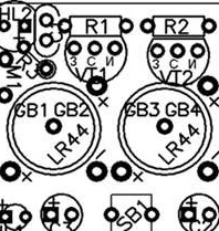
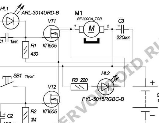
Step one. Schematic diagram of the robot
The robot circuit can be seen in the figure. After inserting the battery, the robot is in the off state, to turn it on, press the SB1 button. Immediately after this, capacitor C2 is instantly charged. The positive plate from the capacitor is connected to the gate of the field effect transistor VT2. In this regard, when the switching threshold is reached, the resistance of the drain-source channel of this channel instantly decreases and a negative potential charge forms at the drain. Well, what happens next can be seen in more detail in the diagram.
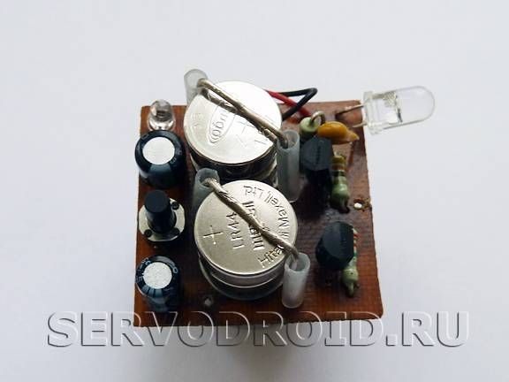
Step Two Mount RGB LED
The LED under the number 1 is mounted on the printed circuit board. In the drawing, this position is called HL2. After the LED is installed, its conclusions must be bent so that the LED is directed to the side. Thus, during operation, the LED will shine not up, but to the side, illuminating the walls. In which direction the light will shine is indicated by a black arrow.
Step Three Mount Battery Mounting Brackets
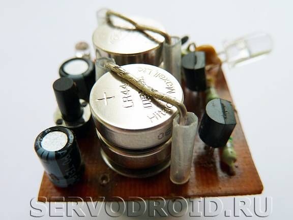
To provide contact between the battery and the robot, push pins are used.One button is installed in the center, in the diagram it is marked as GB1, GB2, and the second is set to position GB3, GB4. To securely fix the contacts, the buttons are soldered with a large amount of solder.
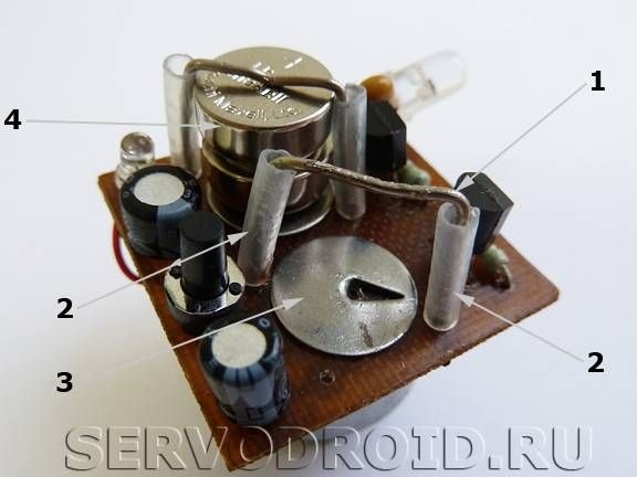
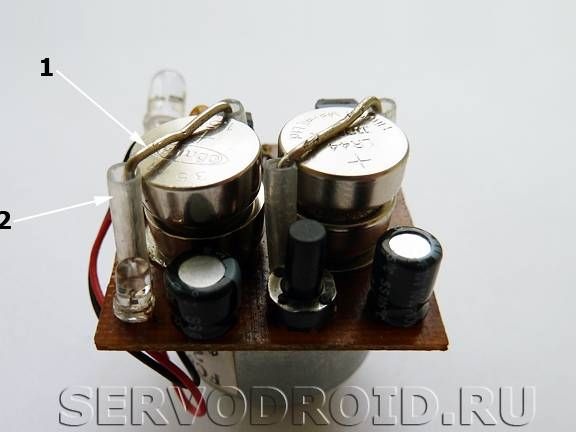
The batteries are installed on the metal button under the number 3. The batteries are fixed with a U-shaped fastener, on which insulators from tubes are worn. The upper part of the bracket needs to be slightly bent with an arc downward, this will allow the batteries to be pressed to the lower contact. Insulating tubes are needed so that the vertical faces of the batteries do not come in contact with horizontal ones.
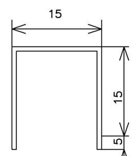
To make a U-shaped fastener, you need to use two paper clips. They need to be bent into a U-shape, as indicated in the drawing. Any tubes can be used, polyvinyl chloride is used here. Their height should be equal to the height of the batteries.
Install the bracket by soldering, for this you need to tin its ends. For tinning, it is necessary to use a neutral, non-washing flux.
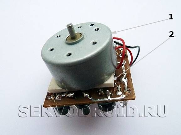
Step Four Install the motor
The motor is installed on the side of the board where the tracks pass, it is located with the shaft down. To fasten the motor, you can use hot glue or double-sided tape. But before you tightly mount the engine, you need to connect it and check the entire system for operability.
Step Five Setup and testing homemade
After assembling the robot, you can test and configure. To do this, you need to install batteries in the robot, they are installed in place of GB1, GB2 and GB3, GB4. In this case, the electronics must be in the off state. After installing the batteries, the robot can be turned on, this is done using the SB1 button. After pressing it, the engine should start working, the HL1 LED will blink, and the RGB LED will also light up.
After some time, the robot will automatically turn off, it will stop and all the diodes will go out. It is then turned on in the same way as for the first time, by pressing a button.
To adjust the time of the robot, you need to experiment with the values of resistor R2 and capacitor C2, they are responsible for this function. If you need to set the maximum operation of the robot, then the capacitance of the capacitor should be as large as possible. In such a simple way you can assemble such an interesting robot.