This article will talk about how do it yourself You can assemble a simple electrostatic motor from improvised means. The peculiarity of such an engine is that it is not driven by an electromagnetic field, as occurs in classical electric motors, this motor operates due to electrostatic voltage. When a burning arc is created from static voltage, then the electrodes are repelled or attracted according to the law of the pendant. Due to this phenomenon, the rotor of the engine begins to rotate. This homemade just demonstrates how you can create such engines. The materials used are very affordable, but a static generator is required for the engine to work.
Materials and tools for engine manufacturing:
- nails (act as a stator);
- foil (used to create the rotor);
- cardboard;
- bearings and axis for the rotor (two washers can act as bearings, and a spoke is suitable for the axis);
- tubes from which drinks are drunk;
- wide adhesive tape;
- Suitable elements for creating an engine frame;
- a device for generating static voltage (some air ionizers are suitable);
- gum, tubules, bushings and other little things.
Of the tools you need scissors, drill, pencil and others.

Engine manufacturing process:
Step one. We make caps for the rotor
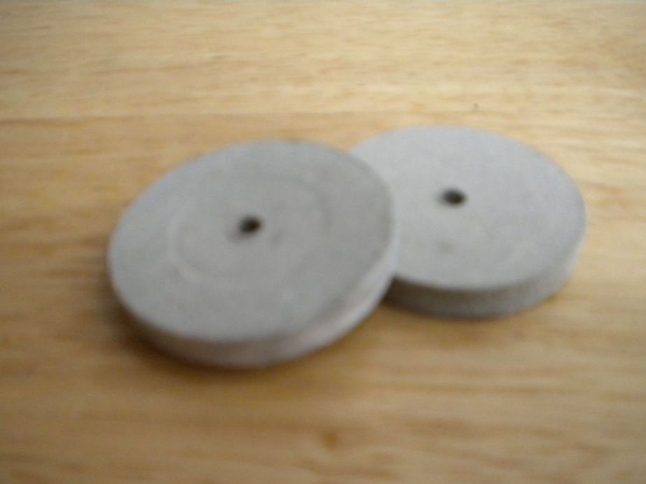
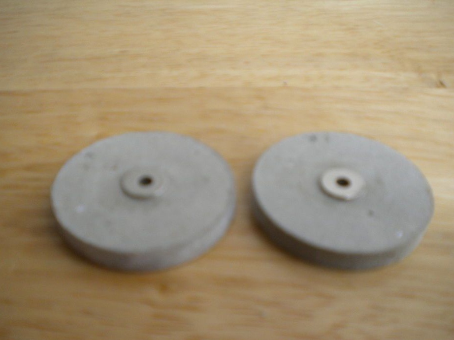
For the manufacture of rotor caps, you will need solid cardboard. Two circles with a diameter of 4 cm need to be cut out of it. Next, in the center of the circles, you need to drill holes. Washers must be glued to the holes, they will act as bearings. If the cardboard is not hard enough, you can cut a few circles, and then glue it.
Step Two Putting the rotor together
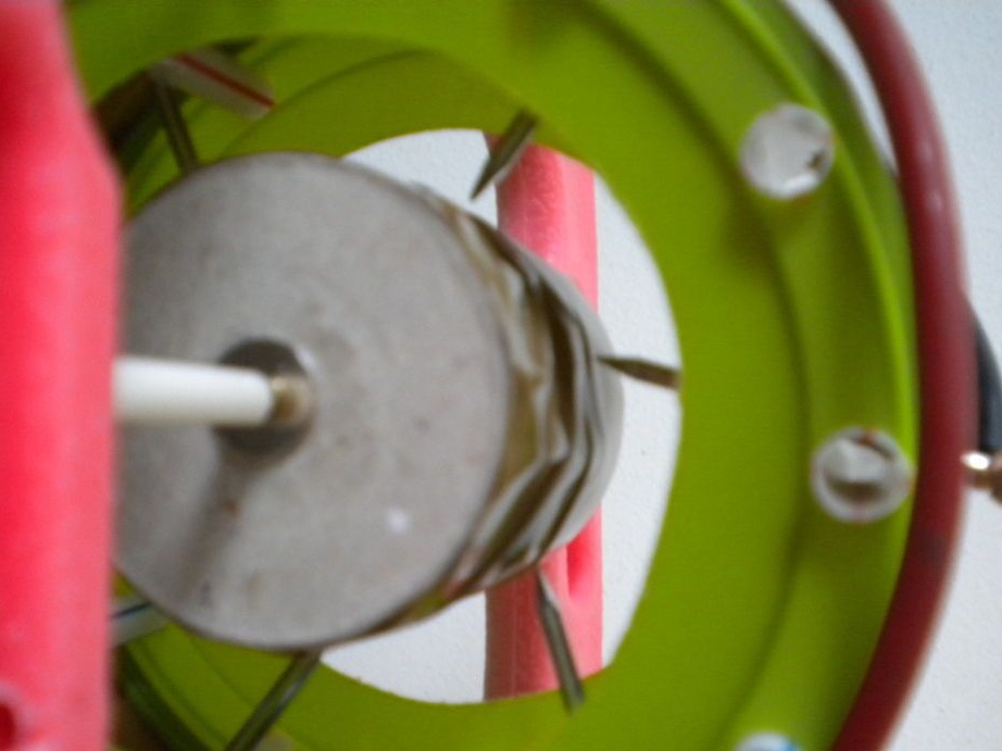
Now the made caps must be put on a flat axis, for these purposes a bicycle spoke is well suited. Then the circles are located at the right distance from each other and are wrapped with tape.The disks must be parallel, otherwise there will be too much friction, and the engine will not work.
After the rotor body is manufactured, you can proceed with the installation of the charge carrier, in this case, the role of the foil. From it you need to cut a tape, 2.5 cm wide, and then fix it to the rotor with glue. That's all, the rotor is almost ready. Now it needs balance, tape is used as cargo.
Step Three We create a stator for the engine
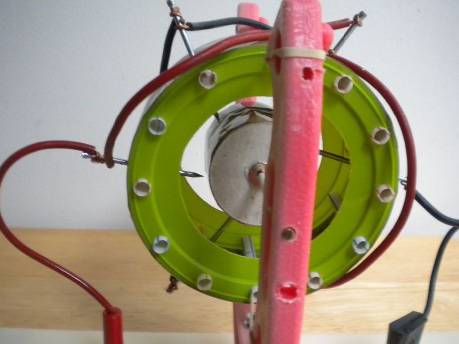
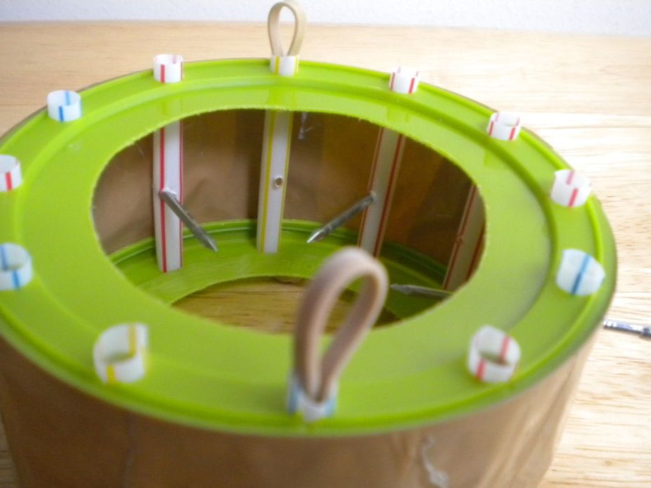
To create a stator, you need two plastic disks or rings, the author for this purpose used plastic covers in which he cut a hole. Still need tubes. Now in a circle of rings you need to drill holes at an equal distance from each other. Subsequently, tubes are cut into these holes, cut to the desired length. Thus, the stator base is assembled.
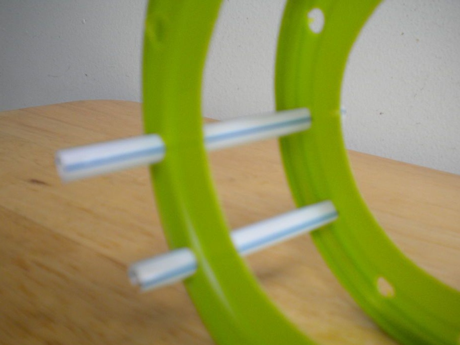
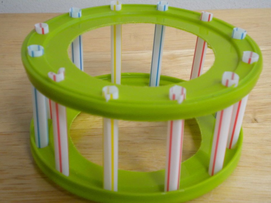
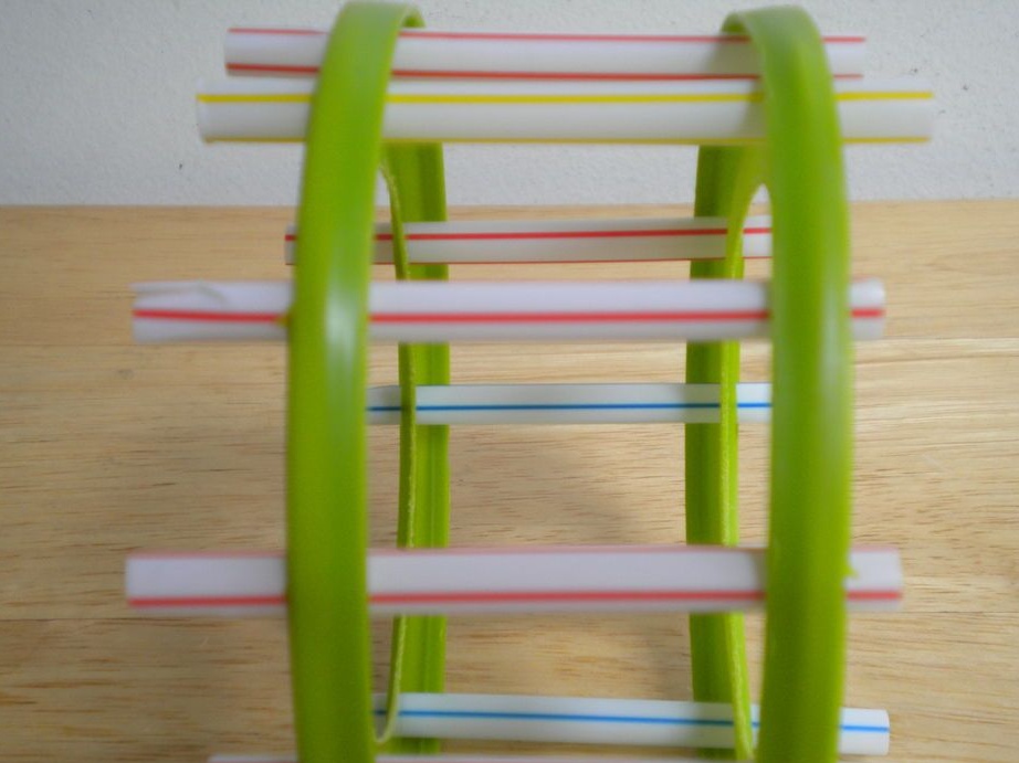
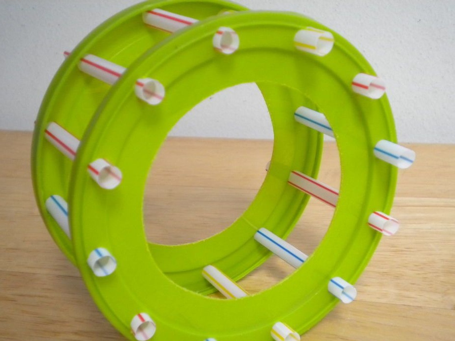
In order to fix the entire structure, again, you need tape. It needs to be wound around the stator. So that the covers do not fall off the tubes, the ends of the tubes need to be bent, as can be seen in the photo. Total tape needs to be wound about 2-3 layers.
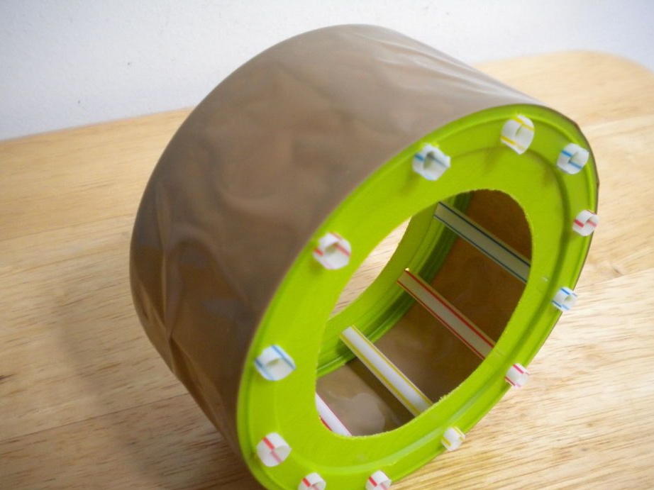
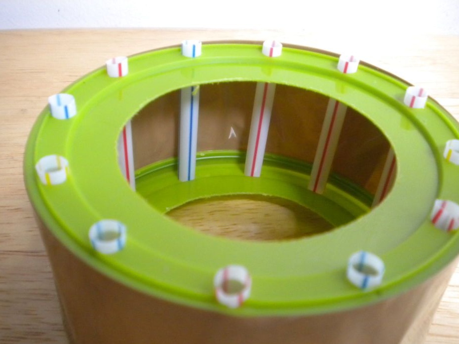
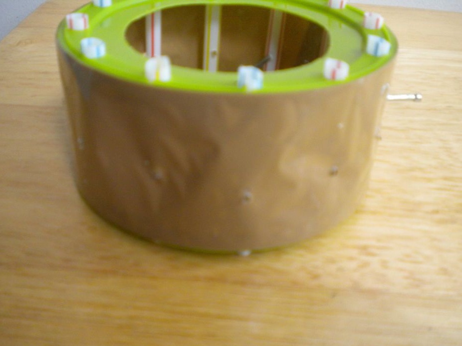
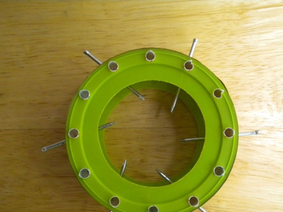
Now you can insert nails, they will act as electrodes, that is, they will transfer charge to the rotor. Nails are inserted through the straws, for this you need to drill holes at an angle in them. It will be possible to more accurately adjust the angle after turning on the engine. And finally, now you need to insert rubber bands into the stator tubes, with the help of them the stator will be attached to the frame.
Step Four Rotor frame
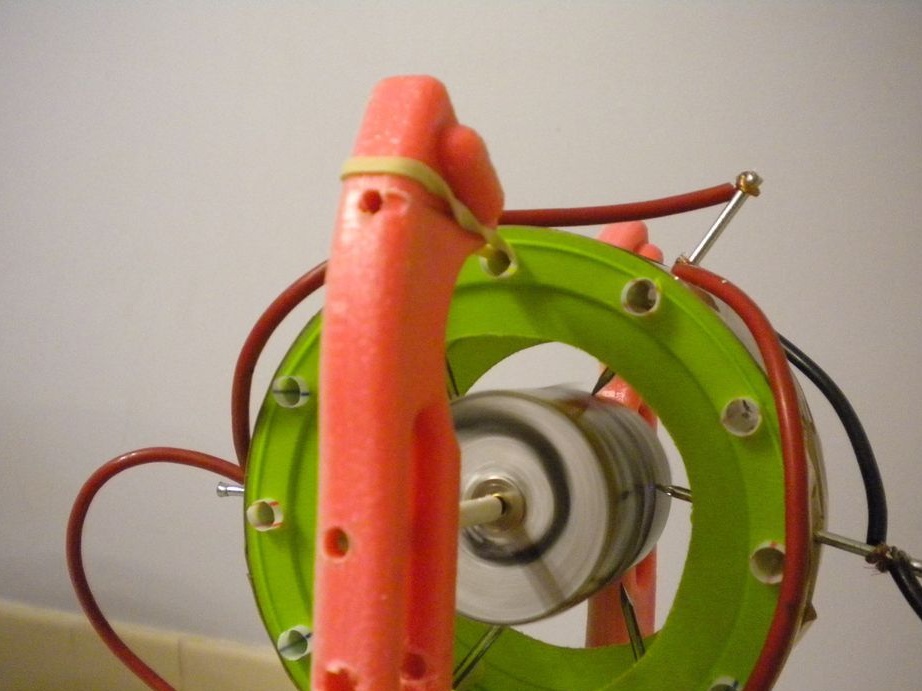
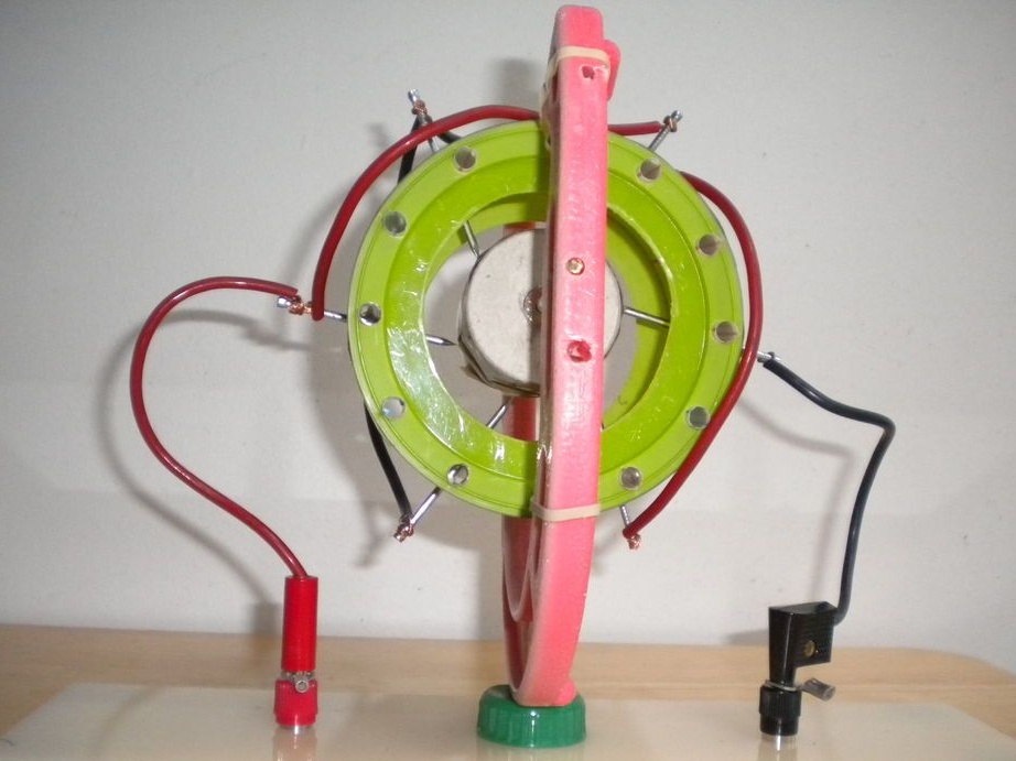
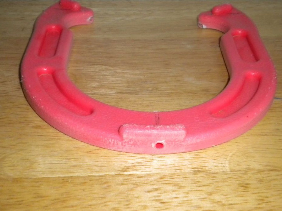
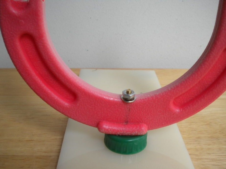
The rotor axis needs to be fixed, any design is suitable for this. The author used a toy horseshoe that was mounted vertically on a piece of plastic. Holes are drilled in the horseshoe, and then an axis is inserted into them. As for the rotor, it is also attached to the horseshoe with rubber bands. As a gasket between the horseshoe and the base, you can use the usual bottle cap.
The most important condition is that the rotor rotates freely on the axis. To limit its movement to the right and left, on the axis you need to wear pieces of tubules of suitable length. You also need to set the correct gaps between the electrodes and the rotor.
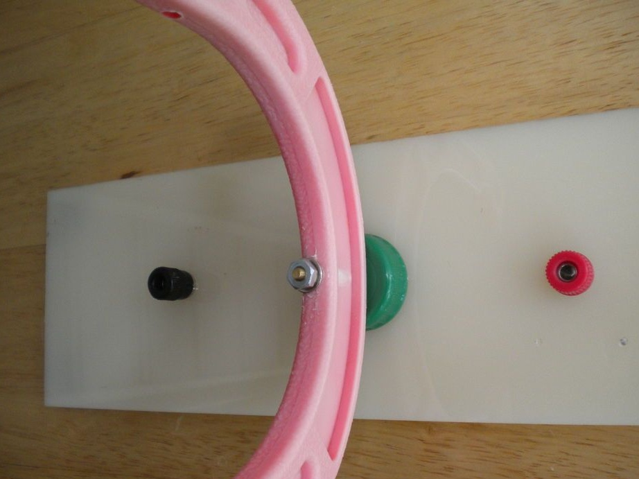
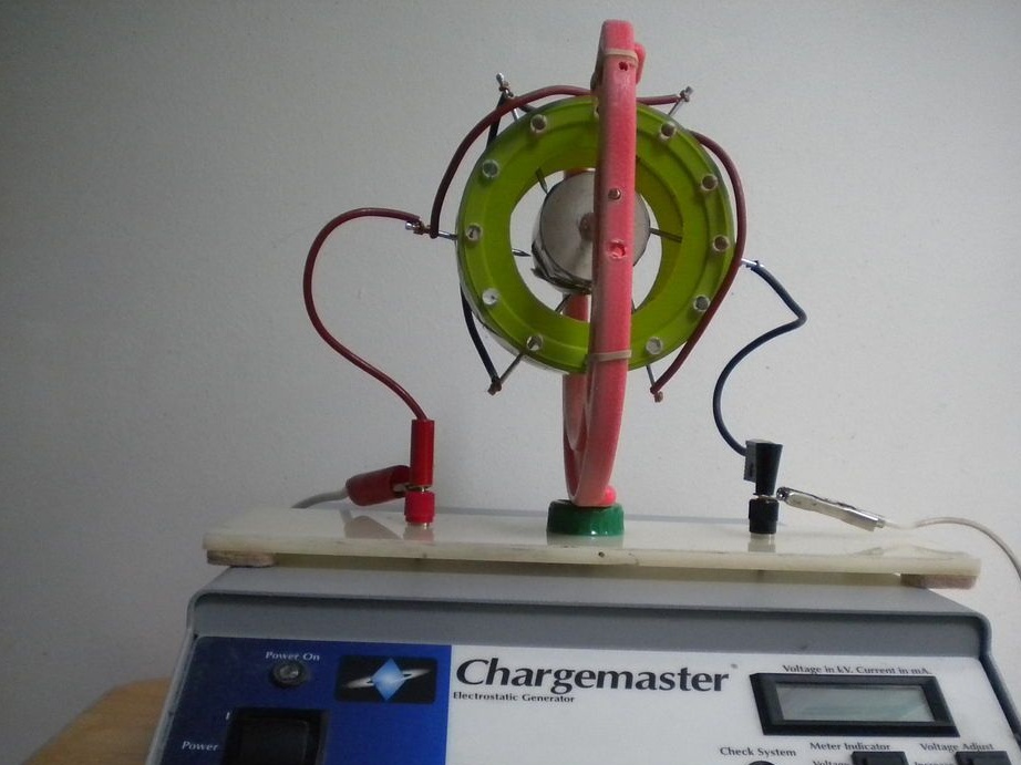
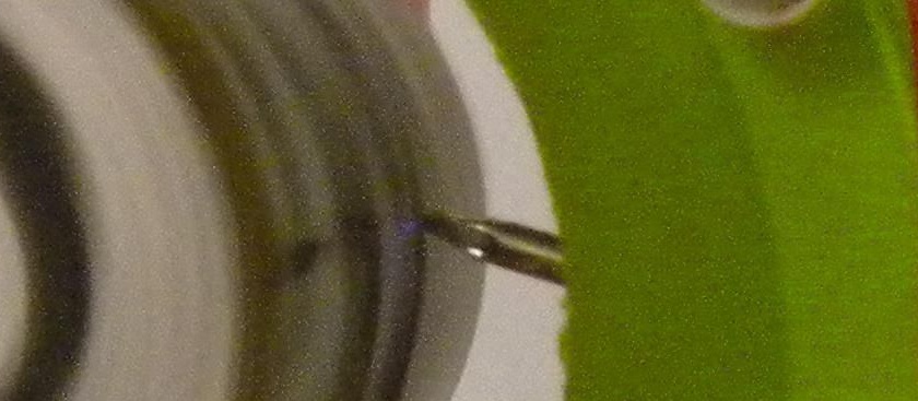
The engine is connected as follows. For one nail, you need to apply a minus from the static voltage generator, and for all the others a plus. In the photo you can see exactly how to do it. Black wire means minus and red wire plus. After connecting, you can try to start the rotor. According to the author, a power of 0.5 W was not enough for the rotor to even move. The optimal power for the engine was 12 kV at 100 microamps. In the photo you can see how a burning arc is formed during engine operation.