
Here are brief characteristics of the device
By the principle of operation, the metal detector is also impulse-balanced.
The operating frequency is 8-15 kHz.
As for the discrimination regime, he uses two tonal voice acting. When iron is detected, the device gives a low signal, and if non-ferrous metal is caught, the tone will be high.
The device is powered from a source of 9-12V.
There is also the ability to adjust the sensitivity and there is a manual detuning from the ground.
Well, now about the main thing, about the depth of detection of the metal detector. The device is capable of detecting coins with a diameter of 25 mm at a distance of 35 cm through the air. The gold ring can be caught at a distance of 30 cm. The device detects a helmet at a distance of about 1 meter. The maximum detection depth is 150 cm. As for consumption, without sound it is about 35 mA.
Materials and tools for assembly:
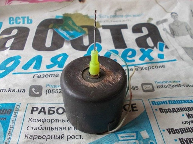
- mini-drill (the author has a home-made motor);
- wire for winding coils;
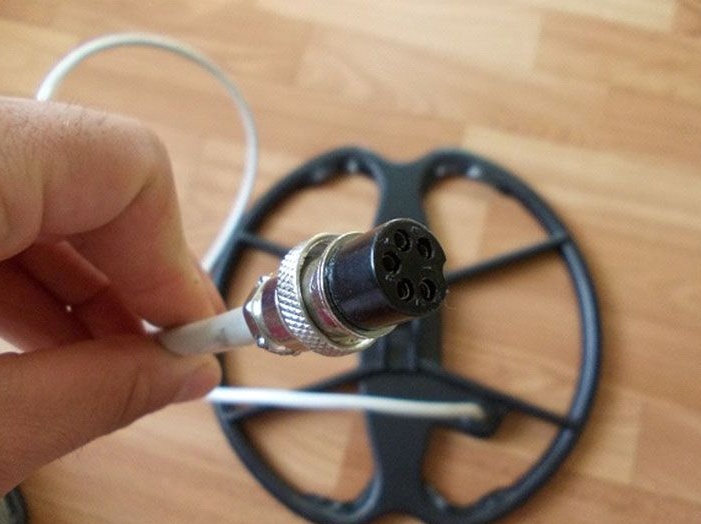
- four core shielded cable;
- soldering iron with solder;
- materials for the manufacture of the housing;
- printed circuit board;
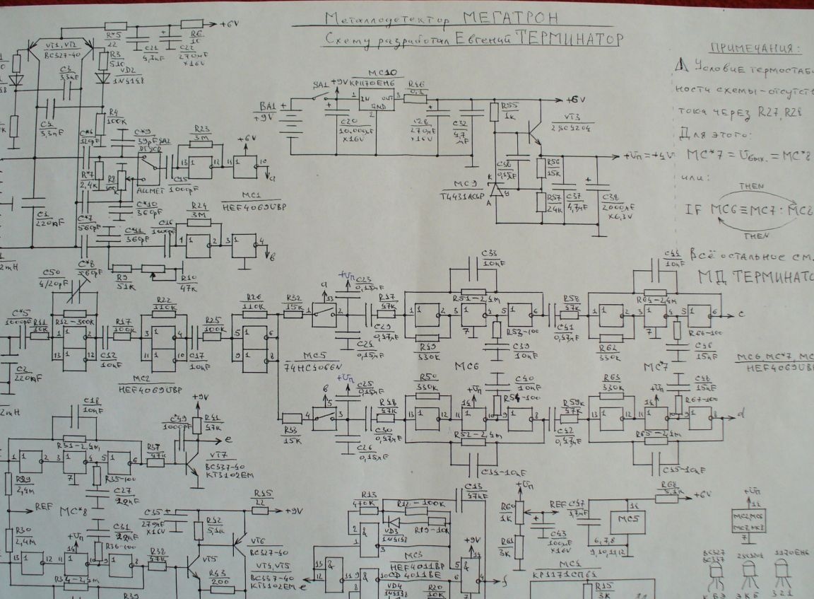
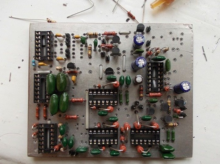
- All the necessary radio components and their denominations can be seen in the photo of the circuit.
The process of manufacturing a metal detector:
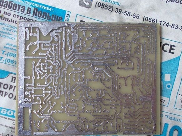
Step one. Board manufacture
The board is made by etching. Then you can drill holes, their diameter is 0.8 mm. For these purposes, the author uses a small motor with a drill installed.
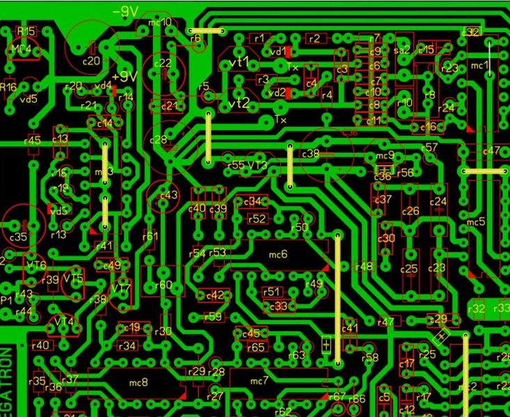
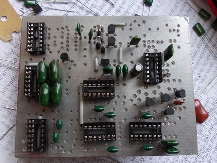
Step Two Board assembly
Assembly must begin with soldering jumpers. After that, you can install the panel under the chip and other solder other elements. It is very important to have a tester for high-quality assembly, which can measure the capacitance of capacitors. Since the device uses two identical gain channels, the gain along them should be as close as possible to the same value, that is, be the same. Both channels of the same cascade should have the same readings when measured by a tester.
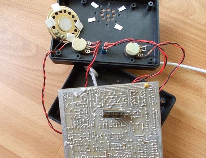
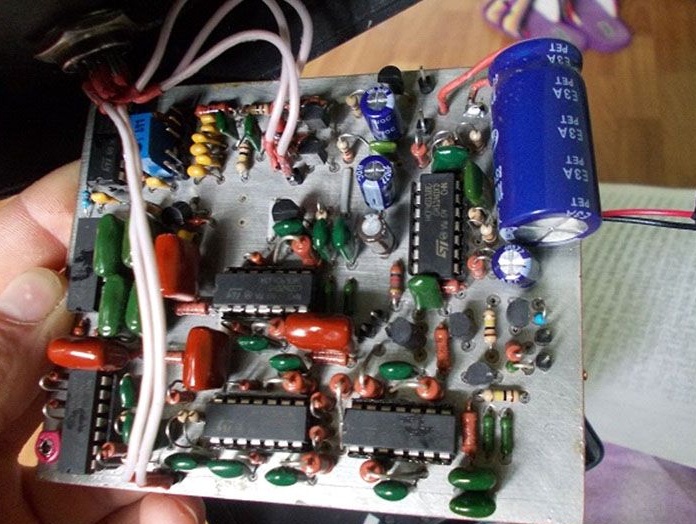
How the already assembled circuit looks like, can be seen in the photo. The author did not install a node that determines the degree of battery discharge.
After assembly, the board must be checked with a tester. You need to connect power to it and check all the strategically important inputs and outputs. Everywhere the food should be exactly the same as in the diagram.
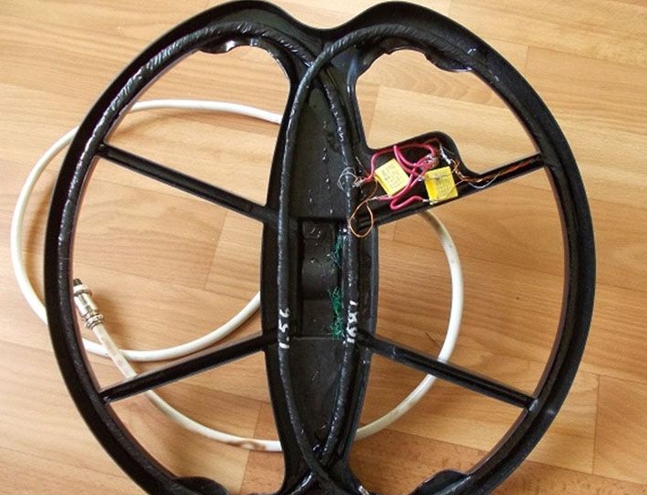
Step Three Putting the coil together
The DD sensor is assembled on the same principle as for all similar balancers. The transmitting coil is indicated by the letters TX, and the receiving coil is RX. In total, you need to make 30 turns with a double folded wire. The wire is used enameled, with a diameter of 0.4 mm. Both the receiving and transmitting coils are formed by double wires, as a result, the output should be four wires. Next, the tester needs to determine the shoulders of the windings and connect the beginning of one shoulder with the end of the other, as a result, the average output of the coil is formed.
To fix the coil after winding, you need to wrap it well with thread and then soak with varnish. After the varnish dries, the coils are wrapped with electrical tape.
Subsequently, a foil screen is made from above, between the beginning and the end, a gap of about 1 mm must be made to avoid a short-circuited turn.
The average output of the TX must be connected to the ground of the board, otherwise the generator will not start. As for the average output of the RX, it is needed for tuning in frequency. After adjusting the resonance, it must be insulated and the receiving coil turns into a normal one, that is, without output. As for the receiving coil, it is connected instead of the transmitting coil and tuned 100-150 Hz lower than the transmitting one. Each coil needs to be configured separately; when tuning, there should be no metal objects near the coil.
To balance, the coils are shifted, as can be seen in the photo. The balance should be within 20-30 mv, but not more than 100 mv.
The operating frequencies of the device are in the range from 7 kHz to 20 kHz. The lower the frequency, the deeper the device will take, but at a low frequency, discrimination becomes worse. Conversely, the higher the frequency, the better the discrimination, but the depth of detection is less. The golden mean can be considered the frequency of 10-14 kHz.
Four wire shielded wire is used to connect the coil. the screen is connected to the case, two wires go to the transmitting coil and two to the receiving one.
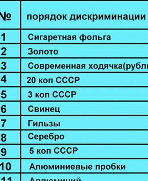
Well, in conclusion, it remains only to configure the device. When the discriminator handle is at a minimum, the device should see all non-ferrous metals. Further, when winding the discriminator, all metals should be cut in order to copper, but copper should not be cut. If the device works exactly as described, then it is assembled correctly.
[media = https: //youtu.be/jbPPzWtr2uE]