
The article will consider an example of how to assemble the simplest arrow speedometer for a bicycle. The board will be used as a controller here Arduino Nano, and as for the arrow, it will be driven by a small servomotor. Speed data is read from the wheel using a reed switch, a proximity switch. However, in a similar way you can make a speedometer for any other transport. Homemade, according to the author, it is very simple and requires a minimum amount of materials.
Materials and tools for homemade:
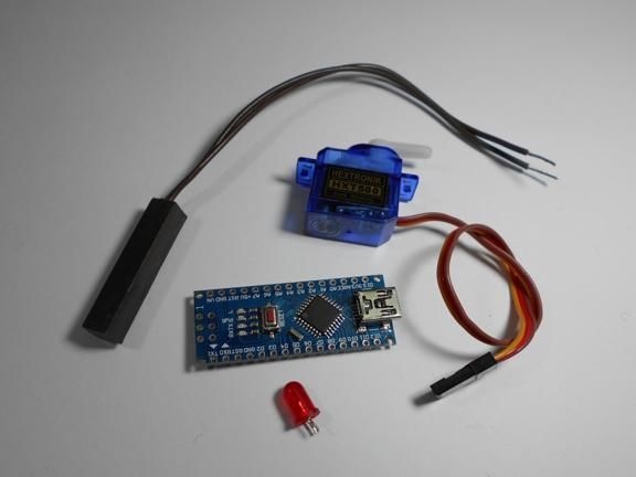
- microcontroller Arduino Nano;
- servomotor;
- reed switch;
- plastic clamps;
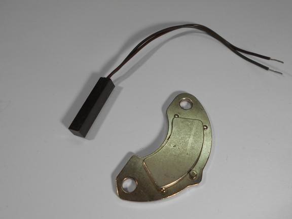
- Permanent magnet (the author used from a computer hard drive);
- red LED;
- one resistor per 1 ohm;
- one 22 ohm resistor;
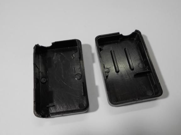
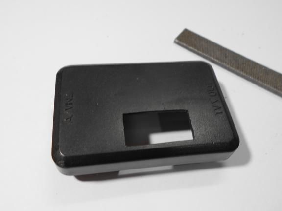
- a plastic box to create a case;
- wires;
- soldering iron;
- materials for creating the mechanical part of the speedometer, cogs, scissors, hot glue and so on.
Manufacturing process cycling speedometer:
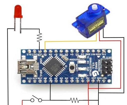
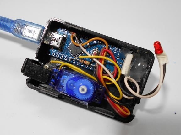
Step one. Electronic homemade scheme
The electronic circuit of the device is very simple and intuitive. All you need to do is connect all the elements as shown in the picture. The circuit has a 220 Ohm resistor, it is used to connect an LED. As for the 10 kΩ resistor, a switch is connected through it.
The servo here will rotate the arrow of the speedometer, and when a certain (according to the author's maximum) speed is reached, a red light will light up on the speedometer.
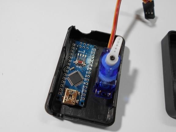
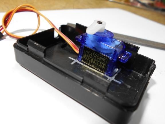
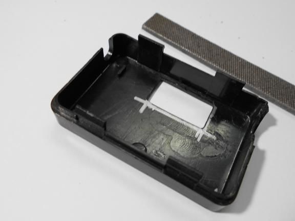
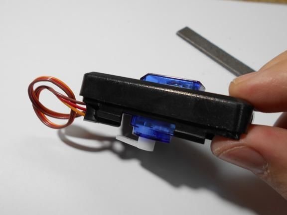
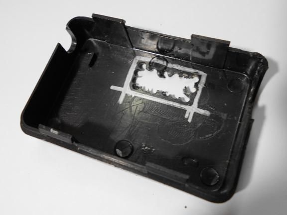
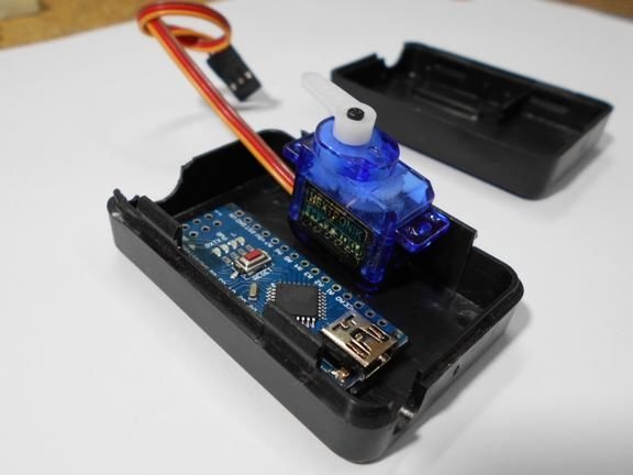
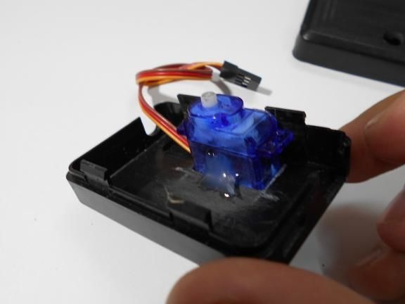
Step Two We install elements in the case
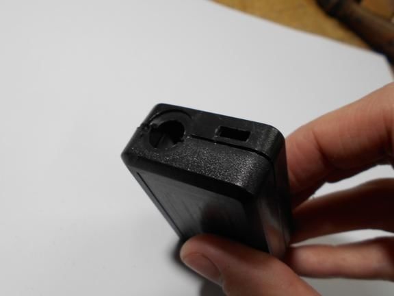
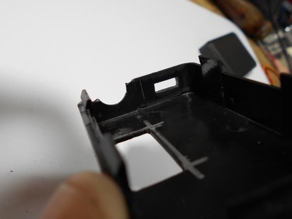
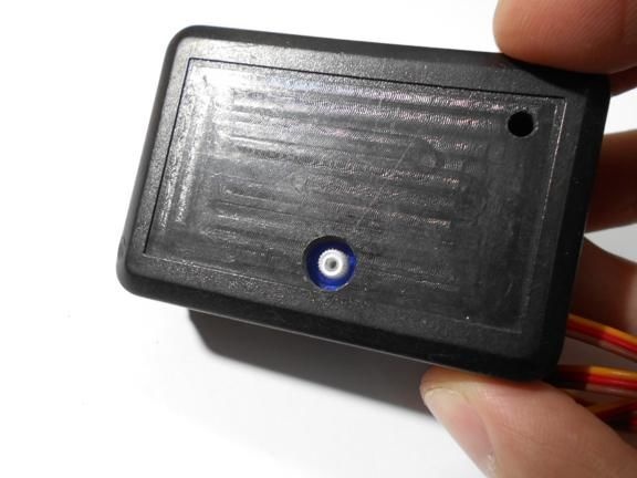
All components are housed in a single enclosure; both a servomotor and a controller are installed here. You can choose any case, the most important thing is that everything fits in it. Next, you need to drill two holes from the outside. The servo motor shaft will go out through one, and a red LED will be installed in the other, signaling the maximum speed. On the other hand, do not forget to make holes in order to remove the USB cable, as well as the wire from the reed switch.When everything is done, all the elements inside must be fixed with hot glue, especially for the servomotor. The case is also assembled with hot glue, it must be carefully sealed against ingress of water.
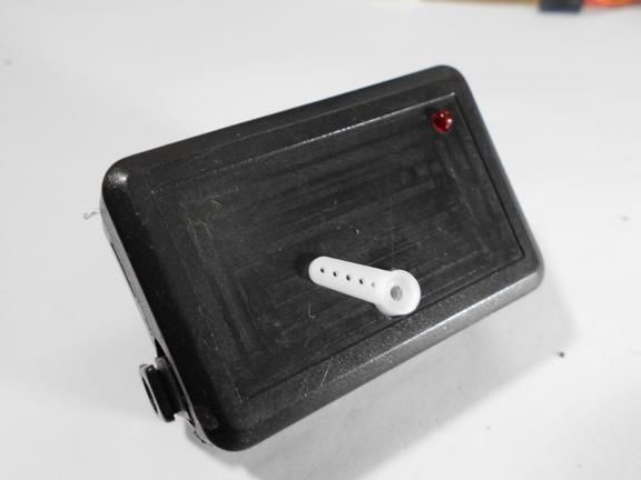
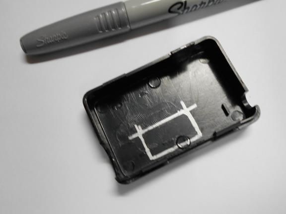
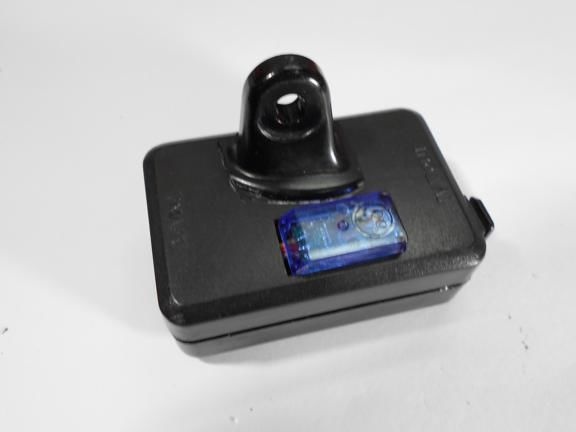
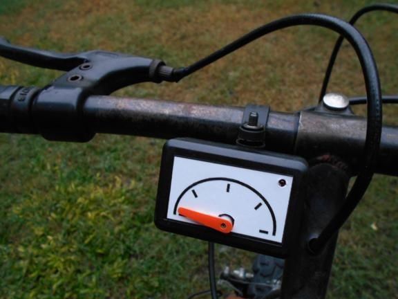
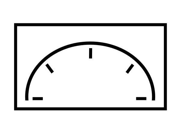
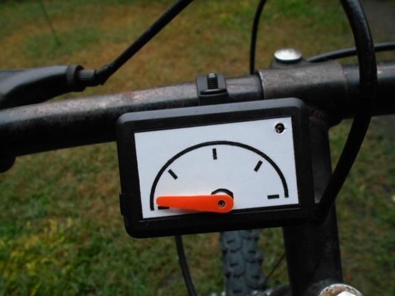
Step Three Making a dial
The dial can be made from a sheet of cardboard or plastic. The author did not draw numbers on it, but simply drew. In the controller, you can set any values for each of these dashes. For example, if the arrow is on the first, it can mean a speed of 5 km / h, on the second 10 km / h and so on. The dial adheres to the plastic case. As for the arrow, it is mounted on the shaft of the servomotor. The arrow can be made both from cardboard, and from plastic or tin.
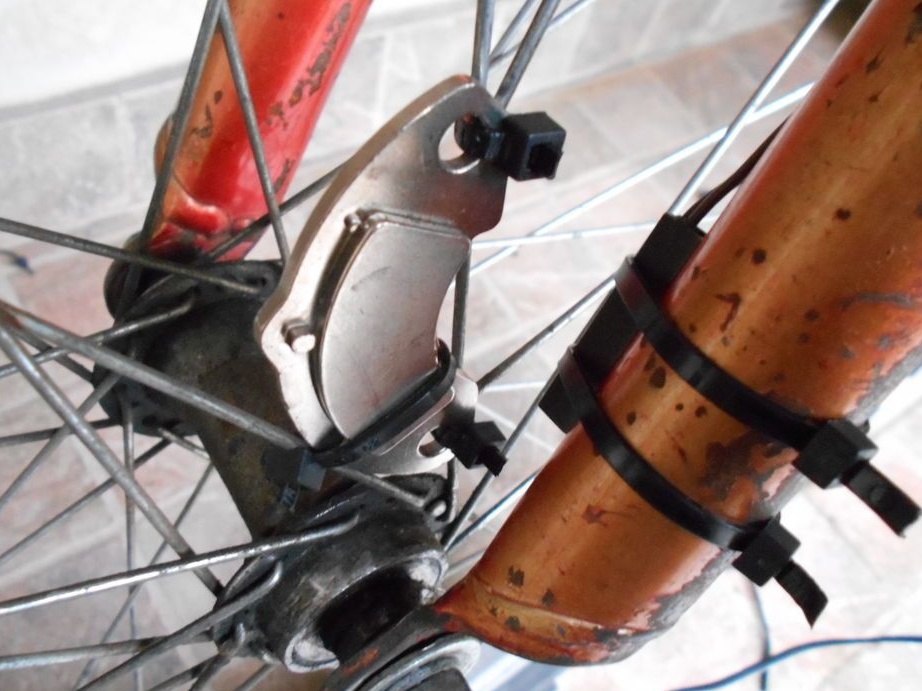
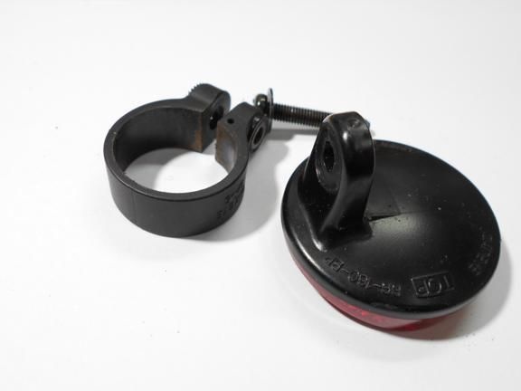
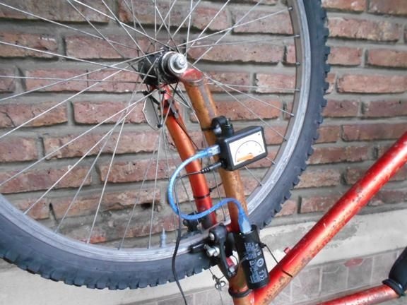
Step Four Reed switch and magnet
The reed switch must be mounted on a fork or frame so that it is at a minimum distance from the magnet. As for the magnet, for these purposes the author used a powerful neodymium magnet from a computer hard drive. As can be seen in the photo, both the reed switch and the magnet are attached using plastic clamps, the magnet is attached to the spokes. The power supply is installed separately, and connected using a USB cable.
After all the elements are installed, you can proceed with the firmware and then check the device.
Step Five Firmware and device setup
In order for the device to start working, you need to fill in the firmware into it, this is done using a computer and special software. The procedure itself is not complicated and anyone can handle it. After flashing, the program needs to be configured correctly. For example, all bicycles have different wheel diameters and the speed of the bike, which is displayed on the speedometer, will depend on this.
The first mark by the author means a speed of 8 km / h, the second 19 km / h, and the third 24 km / h. As for the maximum speed, it is 36 km / h. When this value is reached, the red LED on the speedometer lights up. But everyone can configure the device for any speed for himself.
That's all, the device is ready. Now you can ride and enjoy the work of an interesting arrow, but at the same time the most accurate electronic speedometer based on Arduino.