
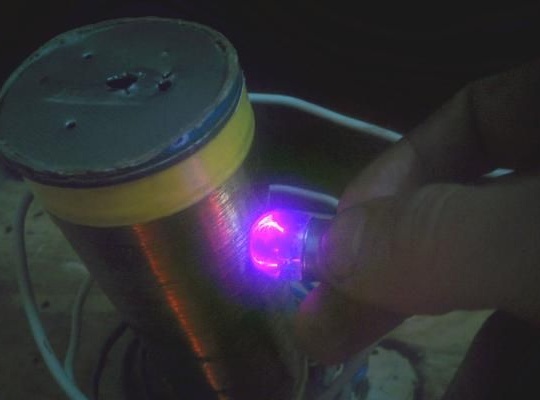
Kacher Brovina in its action is very similar to the Tesla coil, but there are differences in the assembly and in the scheme of the device itself. This is a rather effective device, it allows you to generate a voltage of the order of 1000 volts, and it can also light fluorescent lamps, gases in flasks, emit sparks that you can play with, since the voltage frequency is 250 Hz and the current passes through the skin of a person.
In order to create this device, the author needed some details:
1) Choke for fluorescent lamps.
You can also use the network winding of the transformer, but preferably 100 watts.
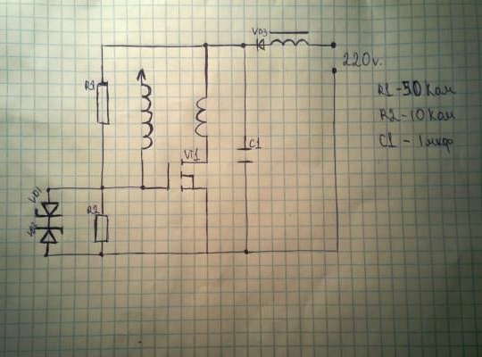
2) Diode 31DQ104L
3) Ceramic or film capacitor marked 105 (1uF) at 400 volts.
4) 50 kΩ and 10 kΩ resistors, although the author allows the use of variable resistors.
5) two zener diodes
6) field effect transistor with a maximum voltage of 350 V
7) Bipolar Transistor
8) Fan and radiator as cooling for transistor and inductor
9) Copper wire with a cross section of 0.1 mm - 0.25 mm.
10) insulated network cable
11) a plumbing pipe with a diameter of 5-11 cm, if you take less, the effectiveness of the device may be affected.
Consider the main stages of the author's work on the creation of this device.
Having decided on the list of necessary elements, the author proceeded to assemble them. The author borrowed capacitors from the boards from the old TV, although they can also be found in power supplies. It was from one of these blocks that a diode was taken, which served there at the entrance as a diode bridge. Zener diodes are also the easiest to find in power supplies. There were no problems with the search for resistors, since they are in almost all boards. In case you can’t find the right resistor value, you can take several and connect them in series or in parallel. Field-effect transistors are more difficult to find, so it was decided to take a bipolar transistor located near the horizontal transformer in the circuit of the old TV. Thus, the author was able to get almost all the details from the schemes of the TV and power supply.
After all the details were found, the author began assembling the main parts of the device.
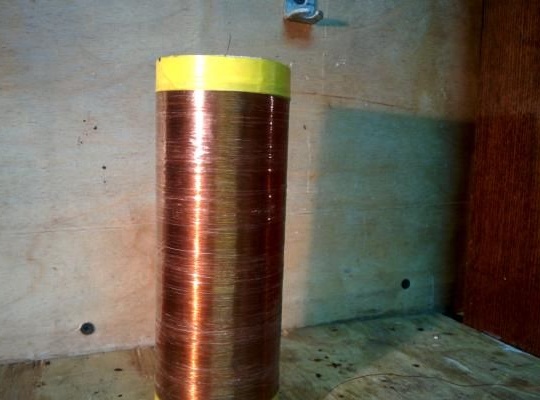
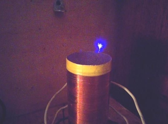
To begin with, the author decided to make a primary and secondary coil by winding copper wire on a pipe. To do this, more than 1000 turns of wire were wound on the pipe, and the author notes that the thicker the pipe and the larger number of turns of wire you use, the better the effect of this coil. It is imperative to wind the wire very carefully, turn to turn, make sure that there are no overlaps of the wire, and it lies in one layer. After the coil is wound, it is necessary to fix the turns. As a fixer, the author suggests covering the coil with varnish, or wrapping it with tape.
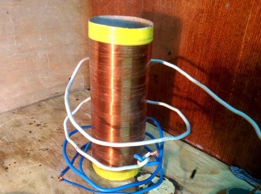
If this is not done later, the coil may unravel and it will have to be rewound, and this process is very laborious and tedious. What the author ended up calling the secondary coil. He then proceeded to create a primary coil by winding a network wire around the secondary coil. Then there will be much less turns that can be made from 5 to 15, and accuracy in this case will only serve for the aesthetic characteristics of the device. The winding of the wire occurs in the same direction in which the wire of the secondary coil was wound.
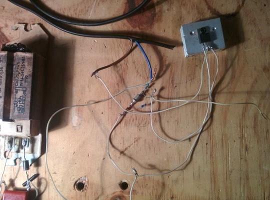
Further, the author proceeded to the assembly of the main circuit of the device. Since there are not so many elements in the circuit, the author decided not to bother assembling the board, but simply assembled the circuit with a canopy. Since the transistor will heat up most of all, it was bolted to the radiator, and the fan was installed on the inductor. Thus, the author organized the air cooling of the device system.
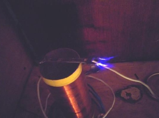
Further, the coils were soldered to this circuit. Then you can turn on the kacher in the 220V socket and it should already work. However, if nothing happened, then perhaps the problem lies in the incorrectly soldered leads from the primary coil. After the conclusions were reversed, everything worked and the author saw sparks that let the wire from the coil.
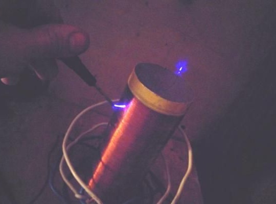
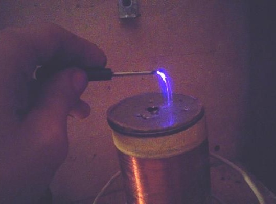
As can be seen from the photographs, the author used a screwdriver to control sparks. You can also put any iron part on the very top of the coil and increase the coil power, which is also shown in the photographs.
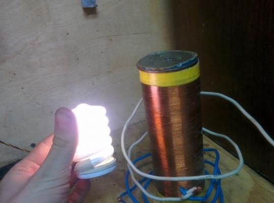
You can also experiment with the lamp, when you bring the lamp to the quality, it will light up. Thus, one can observe the interesting reaction of gases in the flasks when they are brought to a small distance to the quality, it will begin to glow. The author warns that the lamps and bulbs may heat up and burst if overheated, so be careful and follow safety precautions.
The author also plans to create a “singing quality” with a breaker, after he finds the necessary materials for this type of device.
You can find additional information and the opportunity to contact the author at the source link below: