

The circuit of this device is quite simple .
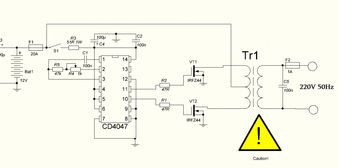
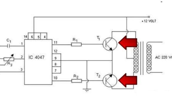
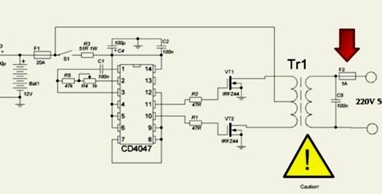
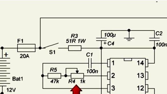
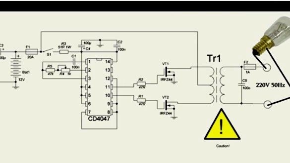
This circuit works on the principle of push-pull converters. The heart of the device will be the CD-4047 board, which works as a master oscillator, and also controls field-effect transistors that operate in key mode. Only one transistor can be opened, if two transistors are opened at the same time, a short circuit will occur, as a result of which the transistors will burn out, and this can also happen in case of improper control.
The CD-4047 is not designed for high-precision control of field-effect transistors, but copes with this task perfectly. Also, for the operation of the device, a transformer from an old UPS for 250 or 300 W with a primary winding and an average point for connecting the plus from the power source will be required.
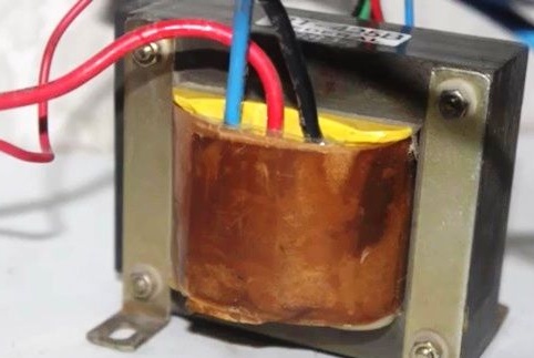
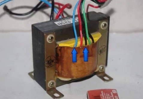
The transformer has a fairly large number of secondary windings, you will need to use a voltmeter to measure all the taps and find the network winding for 220V. The wires we need will give the greatest electrical resistance of approximately 17 ohms, you can remove excess layering.
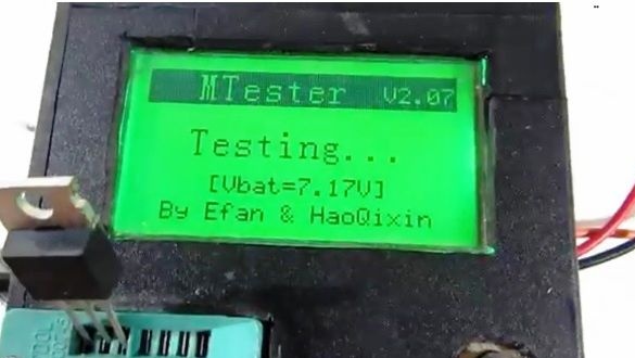
Before you start soldering, it is advisable to double-check everything again. It is recommended to choose transistors with one batch and the same characteristics, the capacitor of the often driving circuit has a small leakage and a narrow tolerance. Such characteristics are determined by the tester for transistors.
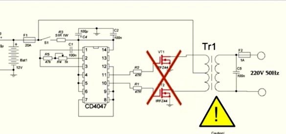
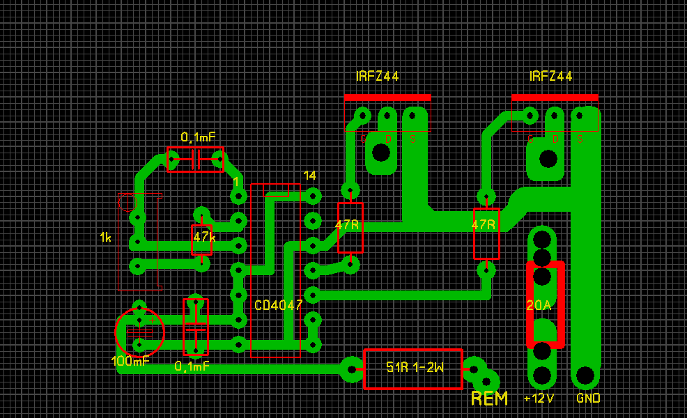
Since the CD-4047 board has no analogues, it is necessary to purchase it, but if you need field effect transistors, you can change it to n-channel ones with a voltage of 60V and a current of at least 35A. Suitable from the IRFZ series.
Also, the circuit can work using bipolar transistors at the output, but it should be noted that the power of the device will become much less when compared with a circuit that uses "field workers".
Limit gate resistors should have a resistance of 10-100 Ohms, but it is preferable to use resistors with 22-47 Ohms whose power is 250 mW.
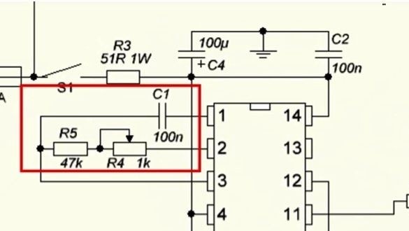
Often, the master circuit is assembled exclusively from the elements indicated in the diagram, which has precise settings at 50Hz.
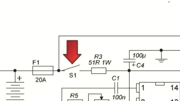
If you assemble the device correctly, it will work from the first seconds, but at the first start it is important to play it safe. To do this, instead of a fuse (see diagram), you need to install a resistor whose value is 5-10 ohms or a 12V bulb, in order to avoid the explosion of transistors if errors were made.
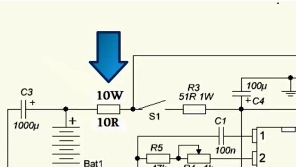
If the device works stably, then the transformer will make a sound, but the keys will not heat up. If everything works correctly, the resistor (bulb) must be removed, and power is supplied through the fuse.
On average, the inverter consumes energy when operating at idle from 150 to 300 mA, depending on which power source and type of transformer.
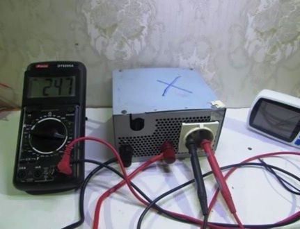
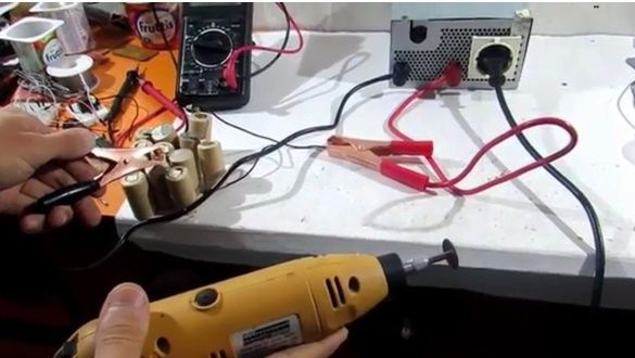
Then you need to measure the output voltage, the output should be about 210-260V, this is considered a normal indicator, since the inverter does not have stabilization. Next, you need to check the device by connecting a 60-watt bulb under load and let it work for 10-15 seconds, the keys will heat up a little during this time, since there are no heat sinks on them. The keys should be heated evenly, in case of uneven heating, you need to look for where mistakes are made.
We supply the inverter with the Remote Control function
The main positive wire should be connected to the midpoint of the transformer, but in order for the device to start working, you need to connect a low-current plus to the board. Due to this, the pulse generator will start.
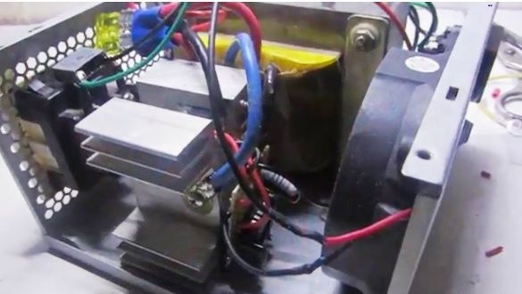
A couple of suggestions about installation. Everything is installed in the power supply housing for computers, transistors should be installed on separate radiators.

If a general heat sink is installed, be sure to isolate the transistor case from the radiator. The cooler is connected to the 12V bus.
One of the significant drawbacks of this inverter is the lack of protection against short circuit and if it occurs, then all transistors will burn out. In order to prevent this, the output must be installed fuse 1A.
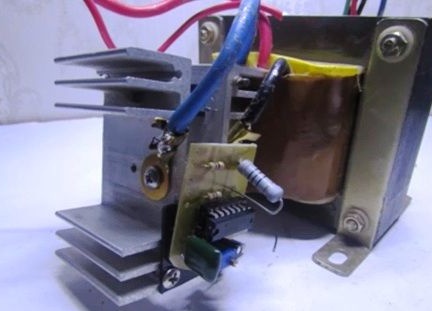
To start the inverter, a button of not high power is used, through which a plus will be supplied to the board. The transformer busbars should be fixed directly to the radiators of the transistors.
If you connect an energy meter to the converter output, then you can see on it that the outgoing frequency and voltage are within the permissible limits. If you get a value greater than or less than 50Hz, you need to configure it using a multi-turn variable resistor, it is installed on the board.

Without load, the device emits a sufficiently strong noise, which decreases significantly with the load, this is considered the norm.
The resulting device is not stable, but almost all household appliances can work with a voltage of 90-280V. If you get more than 300V at the output, you need to connect a 25W light bulb in addition to the main load to the output to reduce the voltage to the required limit.
The author does not recommend connecting asynchronous motors to the inverter.