
This article talks about the modification and refinement of a car charger. The author already had experience in the assembly of primitive pulse chargers, as a child, he assembled one of these with a capacitor isolation in the primary circuit of the transformer (4uF x 400V). The author called it pulsed because the charge was carried out by a modified half-sine wave, while due to the capacitor and resistor, a discharge occurred in the “non-working” half-cycle with a capacity of 0.1 of the charging current. The batteries served with this rectifier for five years, which was quite a lot for the Soviet era.
However, over the years, this charger has become unusable, and the ardor of amateur radio has noticeably diminished, as the author writes, so he decided not to collect, but to buy a cheap automatic impulsnik and bring it to mind through modifications.
Materials and tools that the author used to modify the charger:
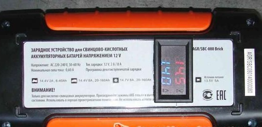
1) AGR / SBC-080 Brick Charger
2) ampere voltmeter
3) soldering iron
4) hot glue
5) electrical tape and heat shrink
6) drill or screwdriver
7) file
Consider the main points of choosing a device, as well as the way it was modified.
The choice of devices is huge, but according to the author, there are no fundamental differences between pulse chargers - automatic machines, with the exception of marketing inscriptions on the packaging and build quality. Therefore, based on the battery power, the author chose the one that was cheaper.
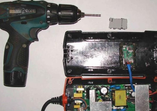
The AGR / SBC-080 Brick charger was taken at a price of 2750 rubles with a desulfation function and a charge current of up to 8A, designed for battery charge up to 160 Ah.

The appearance of the device was credible, since the shell was a high-quality thick plastic, although a sharp unpleasant odor came with it. There are also no complaints about the seams, the rubber is fitted well. In general, the device is quite well assembled, but it does not have an indication of amperage and voltage. Therefore, sometimes a charge with a current of 8A by itself jumps to a charge with a current of 2A, and the LEDs in this case show show a charge, and if the ammeter that the author connected additionally showed no charge.
The author decided to eliminate this problem and bring to mind the purchased device. Of course, you can buy a ready-made charger of excellent quality and with current indication, but it costs several times more. However, thanks to his knowledge of a radio amateur, the author found a way out of how to modify absolutely any charger using an ampervoltmeter, the cost of which is only a couple of hundred Russian rubles, into more attractive and convenient equipment with the quality of work for similar chargers for $ 200.
It does not matter where the ampervoltmeter will be located, it can be either attached inside the device or outside in a separate box if you connect it to the wires that go to the battery for charging. However, it is more convenient to make it integrated into the device itself, if possible.
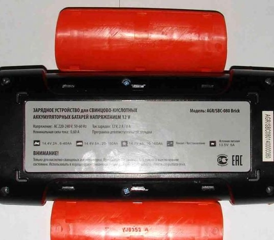
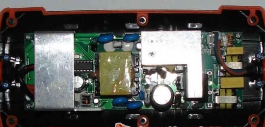
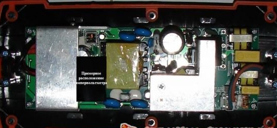
To check this, the author disassembled the plastic case of the device and examined it for the presence of a suitable place in which you can install the board of the voltage meter. As can be seen from the photographs on the front of the panel, it is possible to place an ampervoltmeter only if you change the board itself, so the author decided to place it on the back of the device. The author decided to choose a place for location closer to the charging cables. Thus, having cut the case of the amperevoltmeter with the help of nippers, the author tried to best position the device inside the charger case. Then the author turned the charger over and outlined the hole where the ammeter would be installed.
After that, the author used a drill with a thin drill to drill several holes inside the outlined perimeter of the future window for an ampervoltmeter. In total, about 40 holes were made, which were then combined with the same drill and brought into one large window. All the work took about 15 minutes.
Using a file, the edges of the window were aligned and brought into an aesthetic appearance. After that, the ampervoltmeter was installed in this window and fixed with tremoklei. Thus, the ampervoltmeter is firmly fixed in the window and does not protrude beyond the limiter; moreover, the author managed to save almost all the information located on the rear of the device.
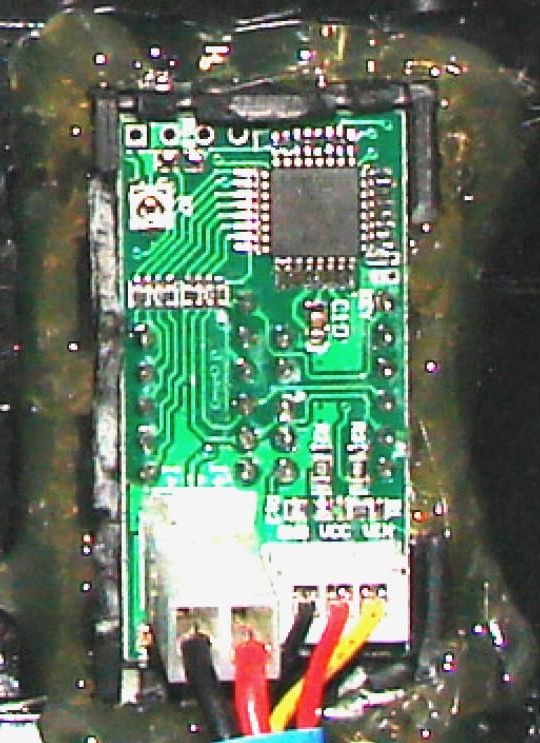
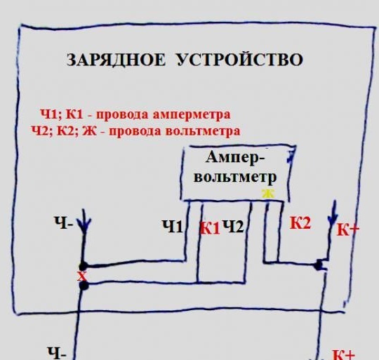
By the next step, the author cut the negative wire from the charger, which in this case is black, and soldered the black wire of the ammeter to the upper part. In the same way, the red wire of the ammeter and the black wire of the voltmeter were soldered to the lower part. The author soldered the red and yellow wires of the voltmeter to the bare plus wire of the charger. soldering places must be closed with heat shrink or electrical tape, after which it will be possible to start testing.
Having connected the terminals (+) and (-) to the battery, the author saw that the device works as intended, since the display of the ampervoltmeter showed its voltage. The current strength will also be displayed on the display when the charger is turned on and the charging mode is selected.
Thus, by cheap and easy modification, the author received an excellent charger. However, it has its own small drawback: the mode switch button is on the front of the device, and the ammeter reading is displayed on the back side. But this is not so important, since the modification did not affect the device circuit itself, but only was soldered to the cables going to the rechargeable battery, so you can remake it so that the ammeter is located outside the device.